Machining
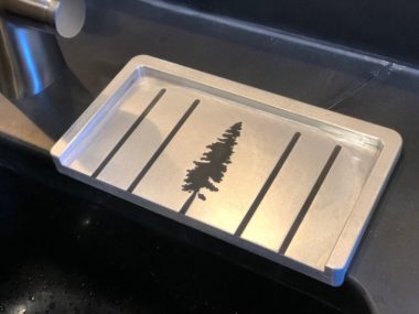
Custom CNC Kitchen Soap Dish Drainer from Solid Aluminum
I’m pretty excited about this project: a custom soap dish with a redwood tree embossing! I recently got a used Tormach PCNC 1100 and this is the first “real” project I made on it. The... [read more]
May
31
2019
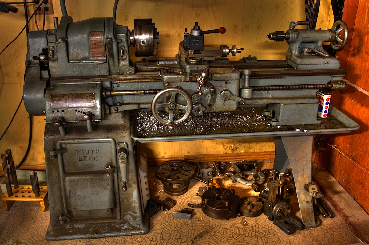
VFD South Bend Lathe Upgrade: Part 1: Motor and VFD selection
The 110v motor on my SouthBend 13” tool room lathe from the 1950’s is slowly dying. It stalls a lot, and I’m forced to take really light cuts, even in aluminum. It slowly decreases speed... [read more]
Jan
17
2018

Video: Wedding Ring from Steel and Pennies!
Lexi and I got married! We made our own wedding rings from some stainless steel that was in my workshop. But the nice added touch was melting some pre-1982 copper pennies on top to add a center accent line.
Oct
26
2017
New Corbin UniBar (unicycle handlebar)
I made a new handlebar for my geared KH26. I was using the KH T-bar, but it feels really flexy and it feels like the seat will eventually break from the pressure I put on... [read more]
Jul
4
2014
Making the LED Cyr Wheel / Roue Cyr – version 1
Here are my rough notes about making my LED cyr wheel (version 1). A Video can be seen here. Edit: 12/28/2013: Here are some problems I am having with this LED Cyr Wheel v1 I... [read more]
Oct
21
2013
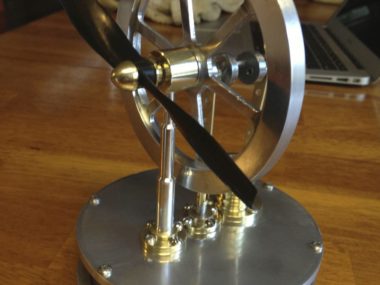
Coffee Cup Stirling Engine
Over winter break I started on a project I’ve been wanting to do for a long time. A coffee cup stirling engine, made from scratch based on plans from Jan Ridders. It “almost works”. The... [read more]
Jan
26
2013
Corbin V-36
I’m working on a V-Frame 36’er unicycle, called the “Corbin V-36“. It’s partially an experiment to see how light I can make it, yet still be strong and not flex. I did a 3d model... [read more]
Jan
1
2013
Plug Bug: Broken brake…
…well, problems come in pairs. I changed my front brake pads about about 8600 miles; they wore away quickly! I didn’t change the rear, as they weren’t as bad as the front. I checked the... [read more]
May
5
2012

Roue Cyr: Making a wheel – skinning
I’m doing a series of videos on how I made my second Roue Cyr (Cyr Wheel — aka: Simple Wheel). Here’s the last in the series…which is skinning. Updated notes: Use pipe clamps to secure... [read more]
Jan
10
2012
New pull up bar
Using the plasma cutter to make stuff… I wanted a new pull-up bar for my house. The old one looked tacky…but how can anything be tacky around your own house if you put it there?... [read more]
Dec
23
2011
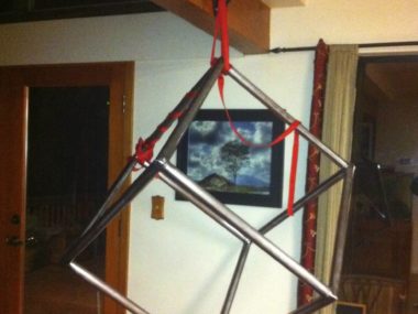
Cube Hanger
I needed somewhere better t hang my cube when I wasn’t using it. So, I made a cube hanger! I used the plasma cutter to cut some pieces of 3/16’ish steel plate (from the scrap... [read more]
Dec
1
2011
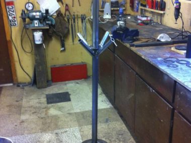
Metal Coat Rack
What a better use for an old VW brake drum? A few in progress shots: Initial sketch and idea:
Nov
15
2011
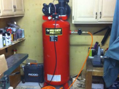
Plasma Cutter
I got a new tool a few weeks ago. A plasma cutter! After doing some research, I went with a Thermal Dynamics Cutmaster 52. It is awesome! I also had to get a new air... [read more]
Nov
14
2011
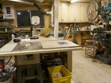
Shop Tour
How about a tour of my garage shop? Grinder: Work desk and tools hanging on the wall: The fan in the window is used to exhaust fumes from welding and other things: Nuts, bolts and... [read more]
Mar
19
2011
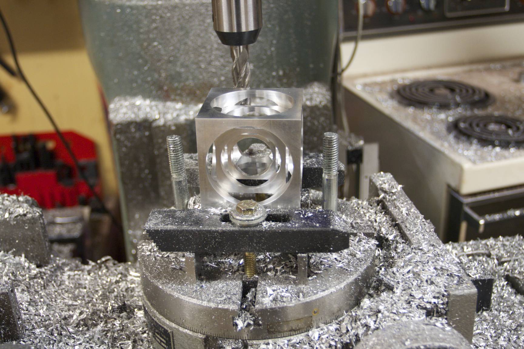
Turner’s Cube
Tuner’s Cube. I made it for my dad for Christmas 2010. Aaron helped me over Thanksgiving break to figure out the details and did some machining on it too. It started out as a ~3.5″x3.5″... [read more]
Dec
27
2010
Metalwork: Wine Glass Rack
Here’s a wine glass rack I made for my dad’s wife, Karen. I made it a while ago, but it was a Christmas present, so I couldn’t post it till after the 25th. It is... [read more]
Dec
27
2010
Plug Bug: Turning the flywheel
An electric motor doesn’t need a big flywheel to keep the engine running. It also doesn’t need the starter gear teeth around the edge. In fact, all it really has to do is engage with... [read more]
Sep
11
2010
New DRO on the Mill
Back in April I bought a Anilam Wizard 411 DRO (Digital Read Out). My old one broke when Jason accidentally moved the X-axis too far (which was totally my fault — I should have checked... [read more]
Jun
3
2010
Steel Bending Jigs
I’ve been working on creating a railing for the upstairs portion of my house. I wanted to create it out of steel and have some cool curves in it. I needed a bending jig, and... [read more]
Mar
26
2010
Recumbent Unicycle
Not a pretty beast, and not easy to ride. It took me thee weeks of practice before I could ride it, and only after that could I “sort of” ride it. No free mounting or... [read more]
Mar
15
2010
Adjustable Unicycle Handlebar
I was never happy with the last handlebar I made for my KH36 road unicycle. It attached underneath the base of my seat, and despite it being carbon fiber it still flexed quite a bit... [read more]
Dec
15
2009
Building a Tandem Unicycle
My last post introducing my Tandem Unicycle originally started out with a step-by-step process of how I built it, but for some reason I lost the post. Here is how I made my tandem uni:... [read more]
Dec
12
2009
Aerial Cube
I just finished another project: the Aerial Cube. Louise and I saw the cube at a circus show last week, and I thought “Hey, I could make one of those!”, and Louise asked “Can you... [read more]
Nov
5
2009
First Machining Project: Vise Stop
Every machinist needs a good vise stop. Here is mine, 100% completely made from raw steel, except for the bolts bolting it to the vise (which are too long — I need to buy new... [read more]
Oct
28
2009
Milling machine tune up
My 1990 Enco Milling machine was starting to get quite a bit of shake at certain speeds. It has a variable speed head, and one of my friends, Bevan, recommended against getting the vari-speed, since... [read more]
Oct
27
2009
MIG welder
I picked up a used MIG welder a few weeks ago. The thing is totally cool; MIG is the way to go (Bronson was right!). I already used it to weld a few little things;... [read more]
Oct
26
2009
One ounce removed off KH Moment cranks
Joseph Campbell came over last weekend to ride trials. He was mentioning how heavy the KH cranks are, so I told him we could quickly mill out some material. I took a deep pocket out... [read more]
Oct
5
2009
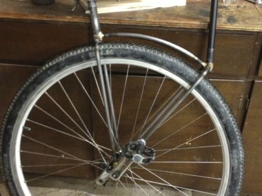
Custom machined V-brake adapter for magura brake mounts
I made this on Saturday out of aluminum: a machined adapter that lets me attach a v-brake to magura brake mounts of my unicycle. The picture below (iPhone quality, sorry!) shows the first one, which... [read more]
Oct
5
2009
Machining a unicycle clamp
I needed a brake adapter for my KH36 to go with a new handlebar I made. I finished the handlebar a few days ago to replace my red one. The red one was made of... [read more]
Sep
5
2009
As an Amazon Associate I earn from qualifying purchases.
(c) 2008-2025 Corbin Dunn
Subscribe to RSS feeds for entries.
50 queries. 0.193 seconds.