How to Design Correctly for CNC VCarve Inlays
There are two basic ways to do inlays with a CNC: you can use a straight bit to machine out a female pocket, and then machine out a matching male plug. This method requires the design to have rounded corners that are at least the radius of your CNC router bit.
The second method is called a “VCarve Inlay”, and it was developed around 2006 using a program called Vectric VCarve. VCarve’ing allows you to use a triangle shaped v-bit to cut out the inlay. This has two advantages: First, can get fairly sharp corners as the bit lifts the router in the z-axis when the design gets too narrow to fit the bit. Second, the bit leaves an angled wall, which allows an angled plug to more easily seat into the inlay, and accommodate some slight variations due to various factors.
I started doing inlays using Vectric VCarve, although I preferred to use Autodesk Fusion for most my CNC woodworking. Eventually I realized I could write a plugin to automate the process in Autodesk Fusion, and I came up with VBit Inlay to do this.
VCarve Inlays done on the CNC router can be tricky to get right. Over the years I’ve developed a lot of notes on what works and what doesn’t work. At one point, I realized the design plays a really important role in how the inlay plug will fit in. I came up with a nice video describing all the things about how a design can affect the inlay:
I didn’t mention everything. In particular, overlapping vectors won’t work in a design.
The main things you have to consider:
- How thin of a line can you do
- How sharp of a corner can you do
- How close can design elements be
I discussed how to figure out these things, and they are based on two factors:
- How deep of an inlay do you want to do
- What bit do you want to use
How Deep Should the Inlay Be
For a decorative inlay, like an art piece or accent to furniture, I prefer about 0.100″ / 2.5mm.
For a functional inlay, like a cutting board, I prefer about 0.240″ / 6mm.
These values see to generally be accepted in the CNC world. I’ve been following some of the inlay masters, like BroInWood, and these are the values that they are using, based on asking questions on instagram and watching his videos.
Bit Selection
Bit selection drastically affects the design you can do. A “thin” v-bit, with a 12 or 15 degree angle, can go a lot deeper than a “fatter” v-bit, like a 30 or 60 degree bit.
VCarving works by lifting the bit upwards when it wouldn’t fit between design elements, so a thinner 15 degree v-bit can achieve a full depth carve in more locations than a fatter 60 degree v-bit. In general, the deeper the inlay the stronger it will likely be and the longer it will last — although, I have yet to actually test this theory out myself, and shallow inlays may work just fine for many years. But a full depth carve will allow the plug to more easily fit in if it is at the same height everywhere, so you may get better results due to that.
How Thin of a Line
In the video I do a series of line tests to emphasize how thin lines will affect the plug fit. One interesting thing is that thin lines with a steep 15 degree vbit will leave the plug too tall in areas:
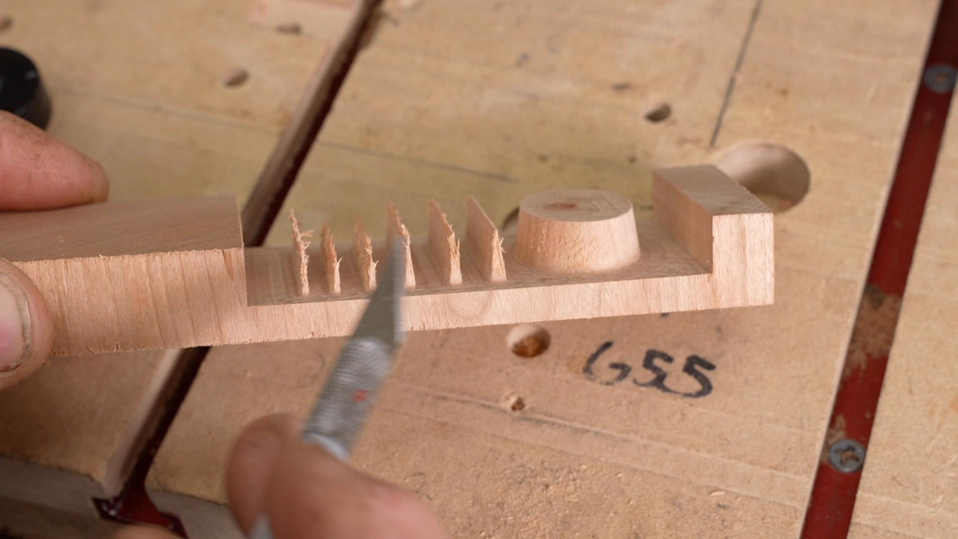
This will cause the plug to not fit in at all, and cause some issues. Doing a test allowed me to figure out what the thinnest line was that I could do with a particular bit, and I’ll include my results below. The video discusses exactly what is going on and what I think is happening.
How Sharp of a Corner Can You Do
A lot of vbits will have a tip radius. Many people are also now using a tapered ball nose (TBN) which obviously has a radius at the tip. Your CNC design must accommodate for this radius, and all corners have to have a matching radius (or larger), otherwise the plug may not fit in quite well at those locations because the CNC will leave a round inside corner.
In practice, it seems to be good to make the tip radius slightly larger than your physical bit’s value. This prevents a hard acceleration into the tight corner, which can sometimes cause a slight overcut. When it is slightly bigger, the CNC will perform more curve cuts, and this is generally a more gentler cut.
How Close Can Design Elements Be
Basically, design elements have to be separated by that “thin line” value you find above. However, there is an exception to the rule: You can have design elements very close together, as long as you machine every-other-one in different steps. In other words, don’t do the side by side ones at the same time; do one in one operation, glue in the plug, then do the other one second. This takes a long time, but you can get really beautiful results by doing this.
Doing elements of the same size at the same time can also be beneficial. An example is the dark spots in the trout below.
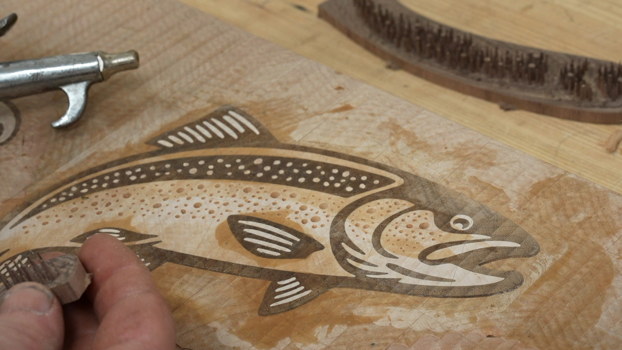
In the photo above, the spot pockets are machined out of the light colored maple wood and they are ready to have the dark colored walnut plug be put in. I could have done these spots at the same time as the dark walnut fish outline, but the size discrepancy and closeness may have caused the spots to not seat in all the way. It was quite interesting, as the small spots quite easily squished down a lot further than other parts of the inlay. Wood is quite malleable, especially then the inlay is tiny!
Results & References
Some of the results that I figured out. These work on my machine, and may need to be tested for your particular machine and setup. The parameters are what I set in Autodesk Fusion, but you can easily use the same values for Vectric VCarve.
- inlay_depth: 0.240?
- inlay_fit_adjustment: 0.070 to 0.080?
- inlay_bit_angle: 15 degrees
- Min line width: ~0.035? to ~0.040?
- Full depth 0.240? line width: 0.068?
- Line width at 0.100? depth: 0.031?
- Min corner diameter: 0.005? absolute minimum, but 0.010? is better
5.26 Degree Tapered Ball Nose / TBN
- inlay_depth: 0.240?
- inlay_fit_adjustment: 0.000? to 0.0010? (try: 0.005?)
- inlay_bit_angle: 10.52 degrees
- Min line width: ~0.048? to ~0.050?
- Full depth 0.240? line width: 0.064?
- Line width at 0.100? depth: 0.038?
- Min corner diameter: 0.020? absolute minimum, but 0.038? to 0.040? is better and what I generally use.
- Thin parts may need trimming
Files/Bits/Downloads that I mention in the video (some are affiliate links):
- Free CAD/Design Test Files – these are the examples that I did in the video.
- VBit Inlay for Autodesk Fusion
- 15 Degree V-Bit
- 5.26 Degree Tapered Ball Nose / TBN – SPE Tool
- 1/8” spiral upcut bit
- 1/8″ downcut bit
- 3D Print Low Profile Toe Clamps
The Trout Cutting Board, shown in the main thumbnail: Trout Cutting Board