Curved Wood Inlays with the CNC
I created the VCarve Inlay Plugin for Autodesk Fusion in order to automate the process on how to create inlays. A few weeks ago I wrote a post all about it: The VCarve Inlay Plugin Details. One of my main goals to was to make it abstract enough to work on non-planar surfaces, as I really like doing curved inlays.
I developed a method for doing curved inlays in Vectric VCarve using the VCarve toolpath and Project to Model. I never really talked about the process; the female inlay pocket is easy to figure out, but the plug takes some finessing, and there are some inherit limitations on how it works. But one problem is Vectric’s toolpath generation for 3D STL mesh models always leaves jagged edges on the side where it approaches vertical. I believe this is just a problem with how Vectric’s modeling engine handles data; it seems to “voxelize” the model data, which leaves jagged edges that are dependent on the model file’s “modeling resolution”, which becomes a compound problem with the original STL mesh model that is essentially already “pixelated” via the rectangular-ish grid used to represent the 3D object. A proper 3D program, like Fusion and Blender, will keep that original mesh data and operate on it when generating toolpaths. They don’t even have a “modeling resolution” because the concept is just silly. Even if I ignore this problem in Vectric, it was incredibly time consuming to create new inlay designs. I wanted something better.
Something better is to design your 3D object in Fusion using mathematical shapes: solid modeling and surface modeling instead of mesh editing (ie: Blender), and eliminating that pixelated mesh problem. The hard part for most people is figuring out how to do the CAM and toolpath generation in Fusion. There are tons of knobs you can turn, and it hard to know what does what, and what is even important. Vectric makes it really easy and simple.
Since I really wanted to use Fusion, I took the time to figure out a way to do the curved inlays. While I think I’m the first person to solve this problem, I don’t really know for sure, and anyone who proclaims they are the “world’s first” at doing something is just hadn’t stumbled across someone else who already did it.
Creating curved inlays is almost identical to creating 2D flat inlays. In 2D inlays you will machine off the top of your stock at a particular height. In 3D inlays you machine the 3D surface off, and use that as your starting stock’s top. For the plug, how far it sticks above your actual design is how deep the inlay will go. That’s really the basics of it, but tricking Fusion into doing this was the hard part. The main solution was to model up the stock at this increased height.
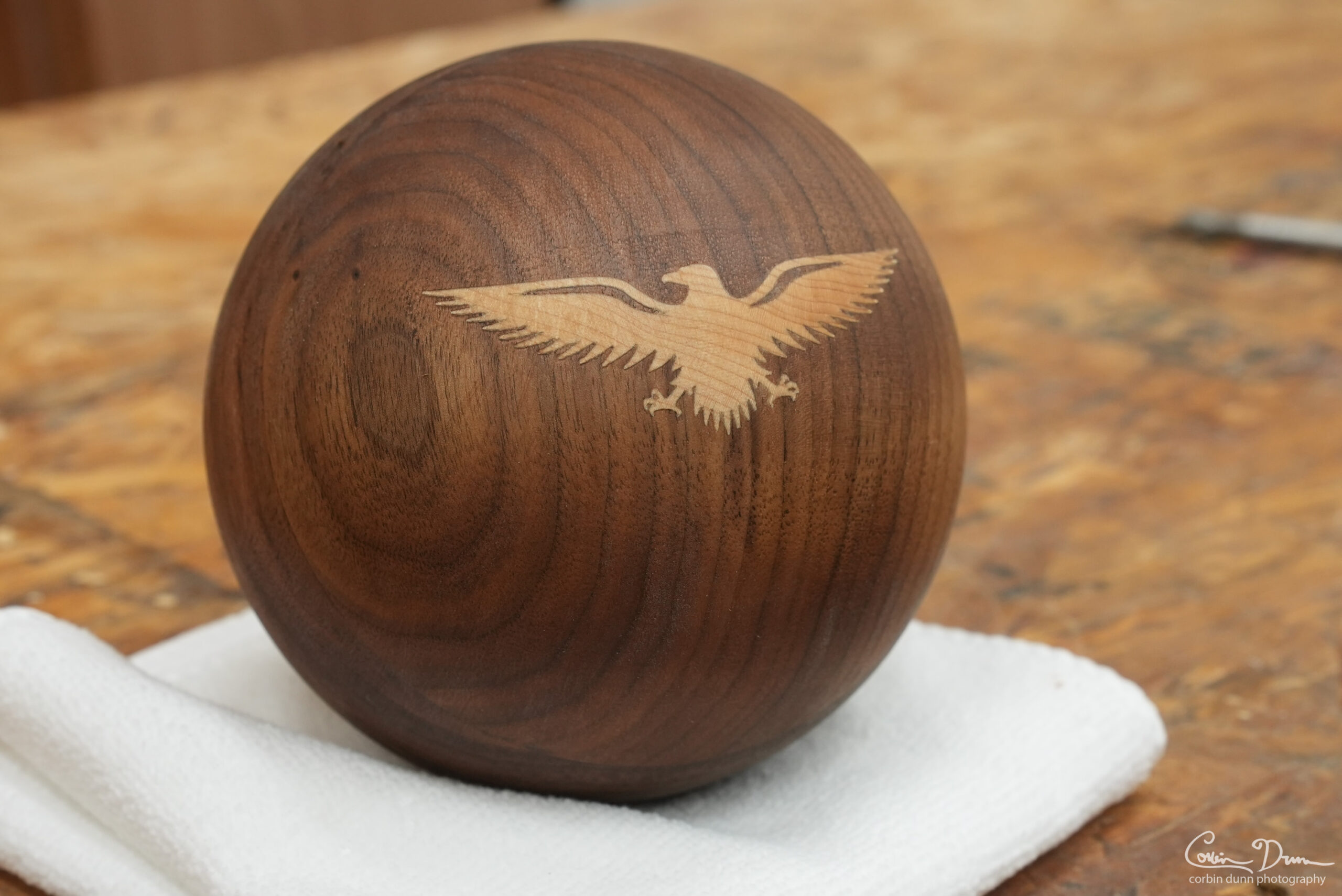
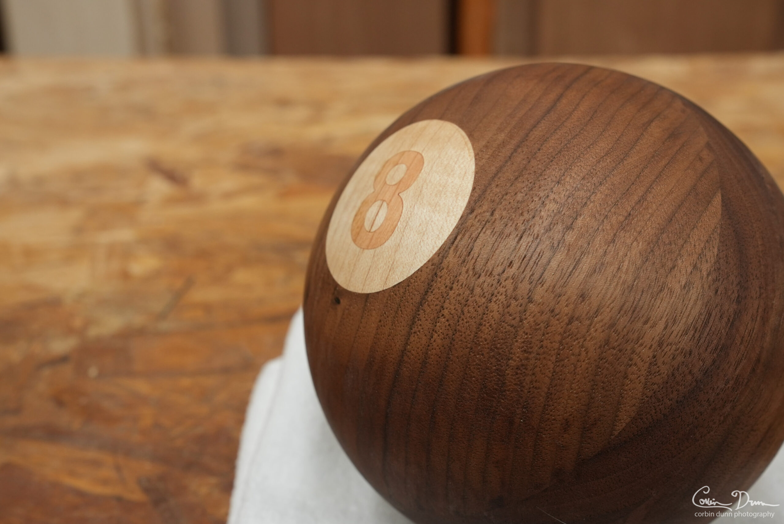
I’ve done a few spatulas with the new inlay process, and it is awesome! I can easily add in a new design and be carving it out in almost no time at all. But the real test was the walnut sphere. I was curious if I could easily make such a shape, as a sphere in itself might be a difficult CNC project. And then adding an inlay into it would be the perfect test of my new plugin.
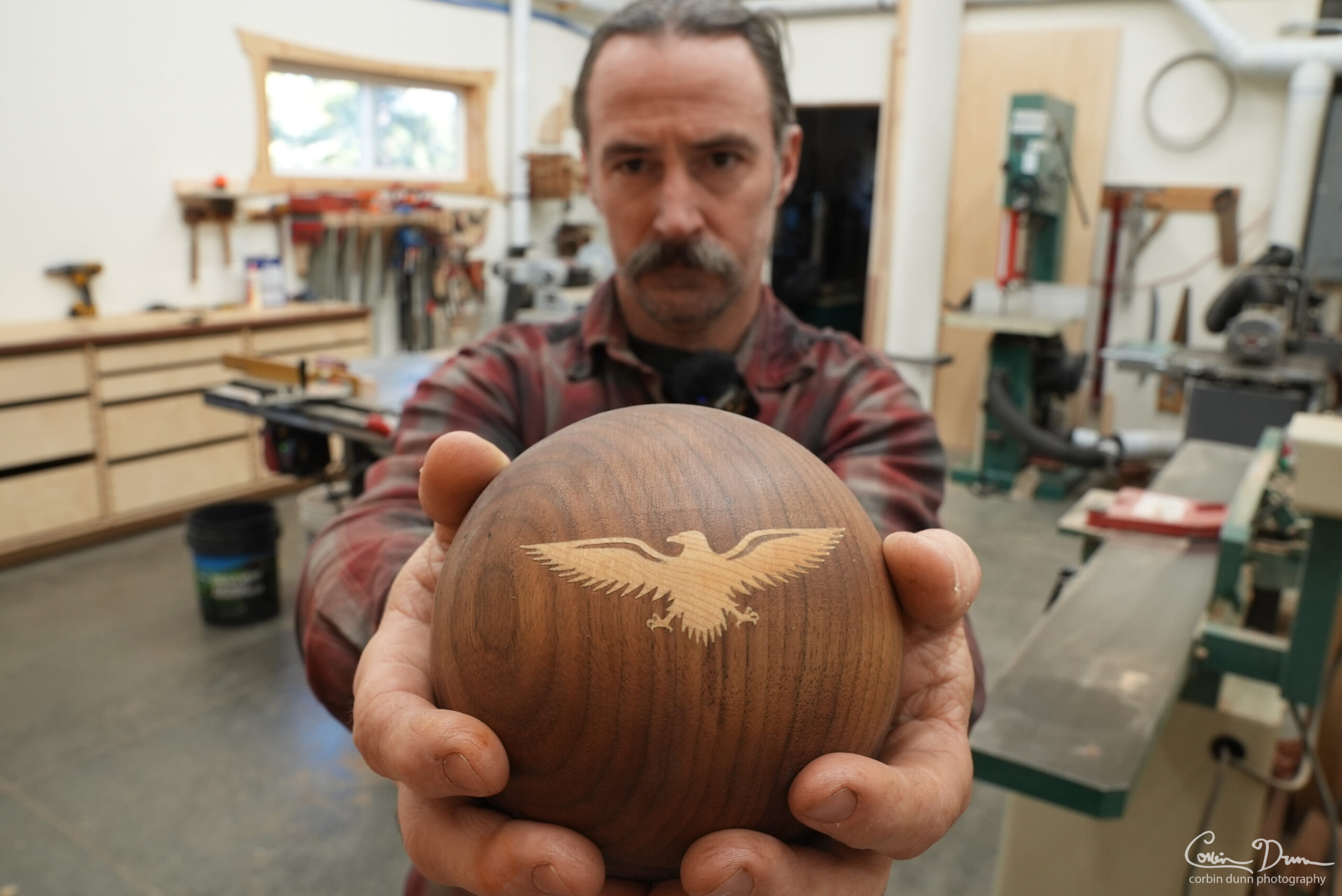
I’m incredibly surprised at the amount of detail I got with this eagle! The male plug got a lot of chipout when I did it in face grain, so I re-ran the toolpath in end grain and got a much better result. The walnut did chipout a bit; there aren’t any really visible gaps because the glue filled it in, but if you were to zoom in really close you could see areas that lost some detail. Still..quite amazing.
As usual, the files are available for this project (free download):


[…] I’ve been doing wood inlays for quite some time, but most of them have been small inlays on curved surfaces, such as at the end of my wood utensils. These have been good practice for building up to making something larger, as it is generally harder to do small detailed inlays and it is even harder to do a curved inlay. […]