Framing a Woodshop – The Truckee Workshop Part 8
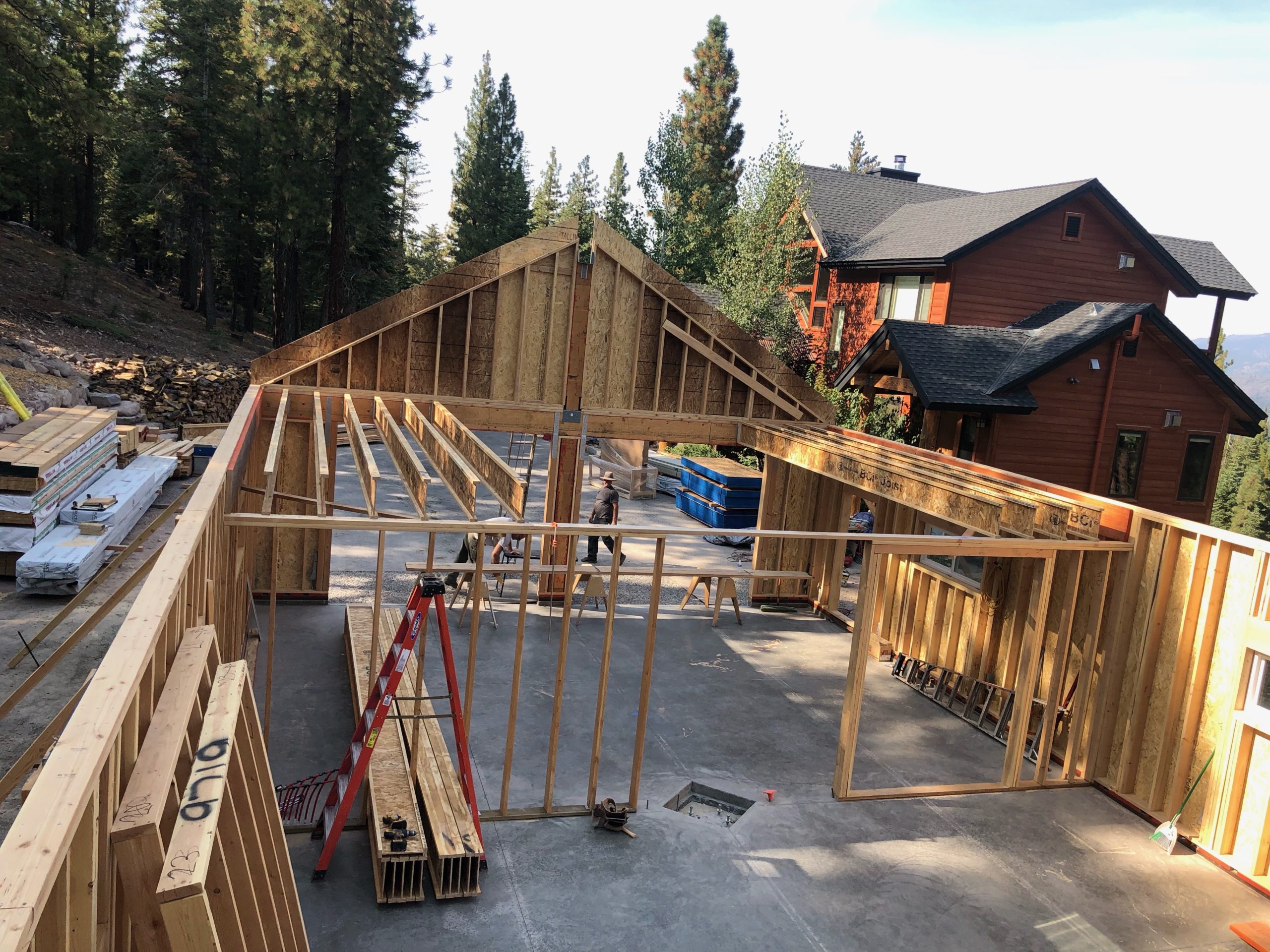
Once the wood was delivered it was go time for construction. I needed to get it roofed before winter started rolling in, and the pre-framed walls gave me a pretty good head start, but this wasn’t a task I could do alone. My in-laws live in Truckee and have a neighbor named Chris that does general construction. He has a friend named Neville, and the two of them are highly skilled individuals who can read plans and build from them. This wasn’t something I had ever done, and it was all new to me. Eventually I became proficient at reading plan details, but I was pretty lost at the beginning. The idea was to have Chris and Neville help me build the building, along with two other construction labor helpers – Josh and his dad Jim. In general, we had four or five people on site on a given day, depending on who was available.
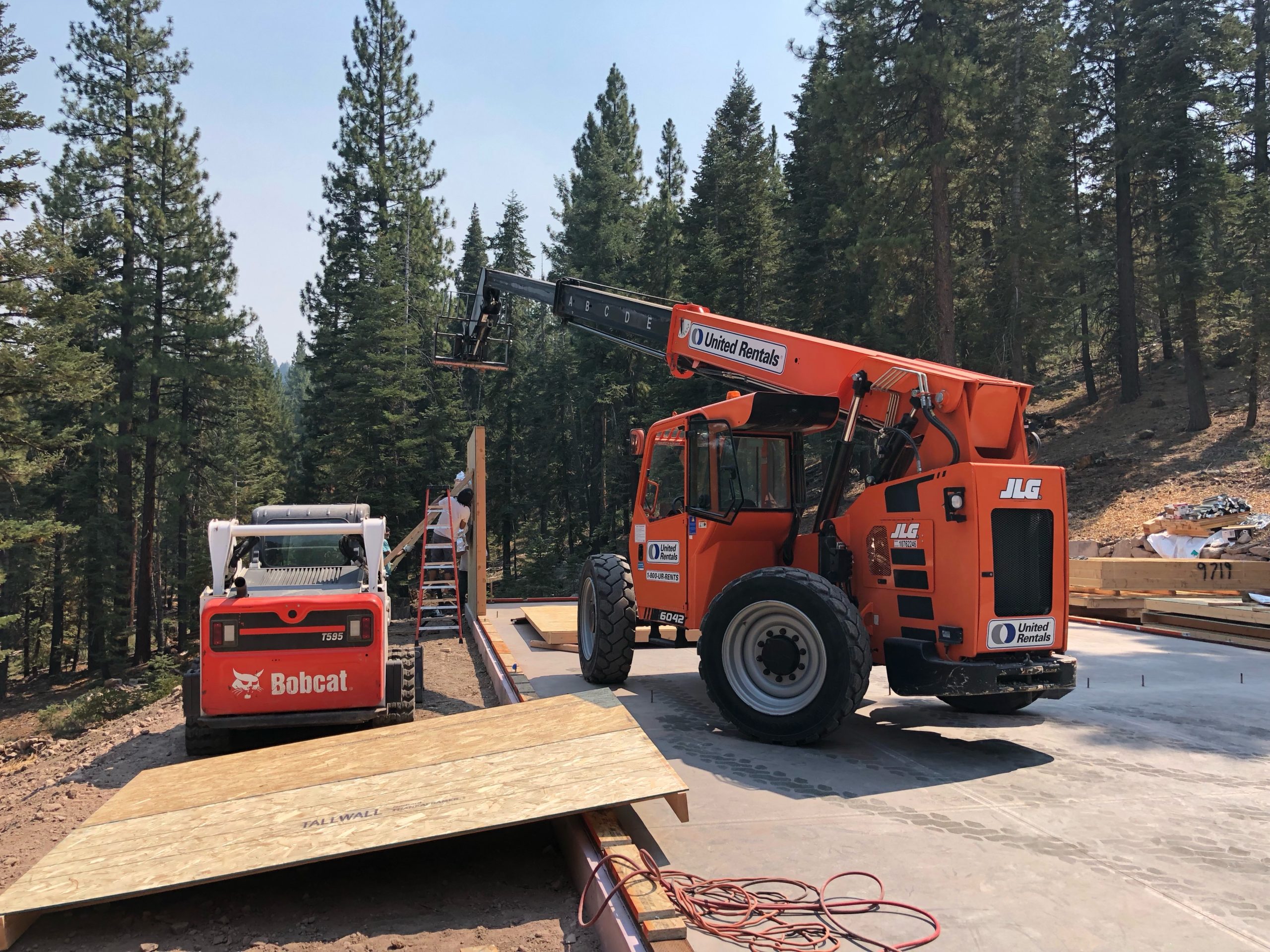
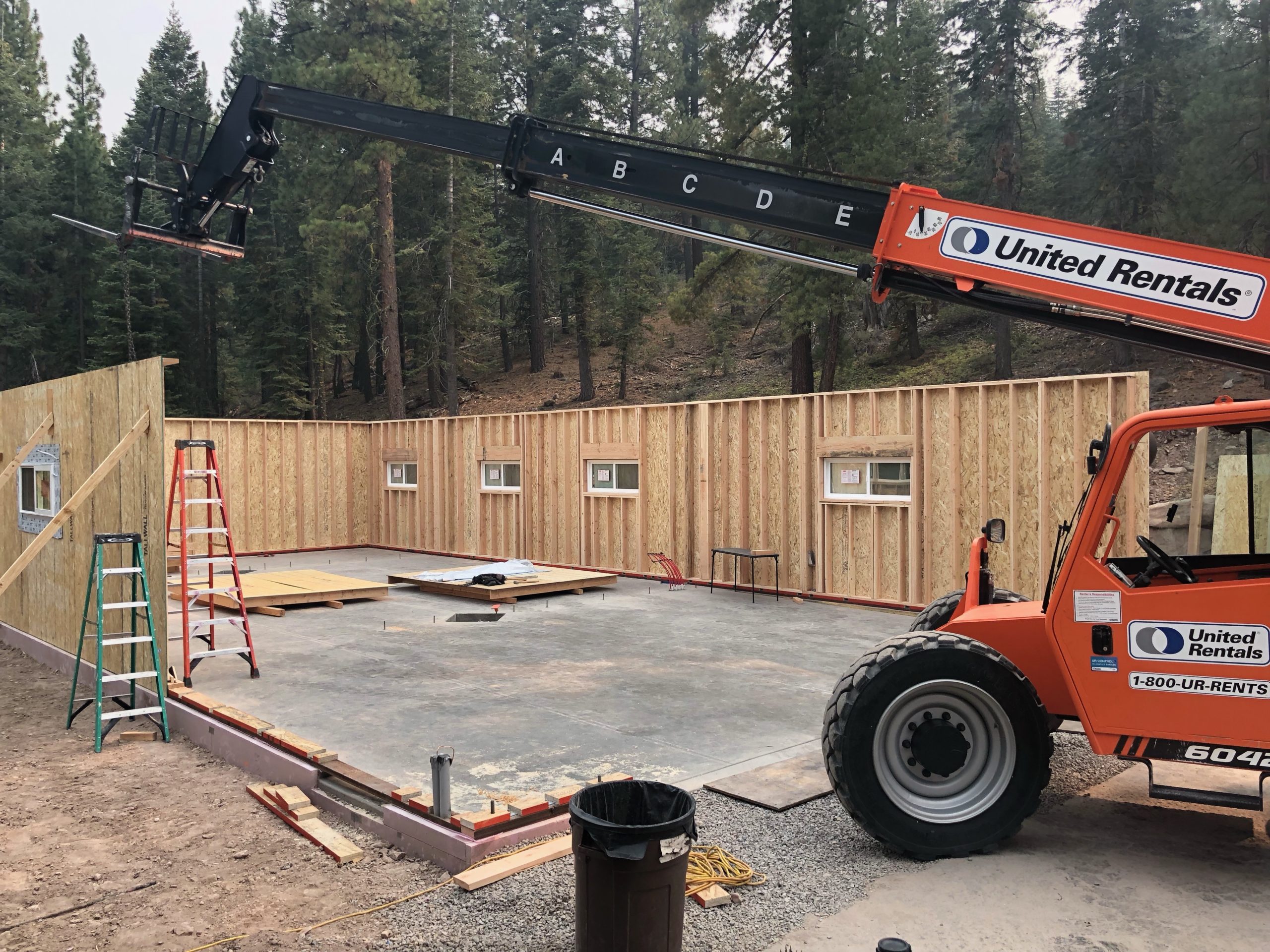
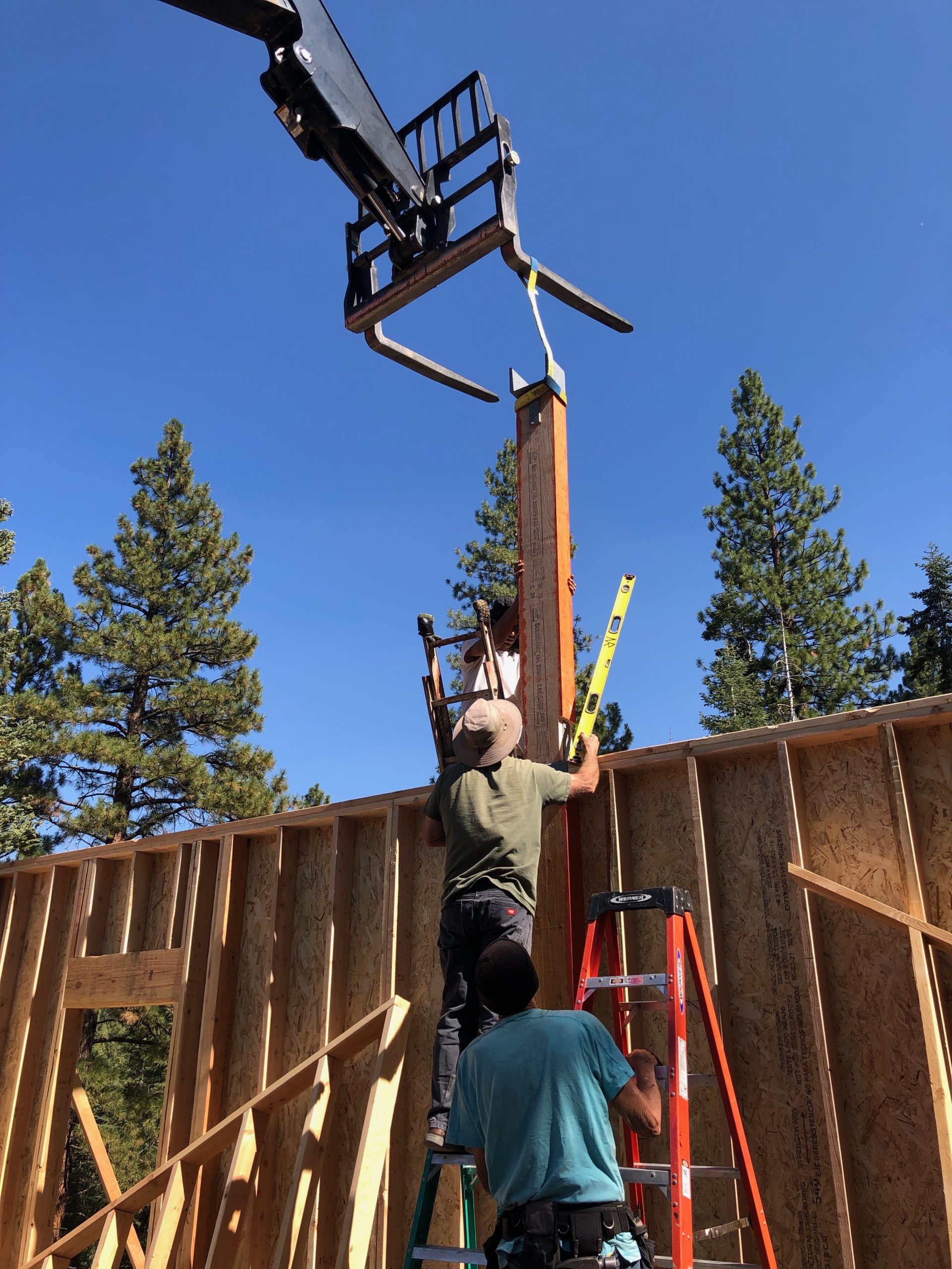
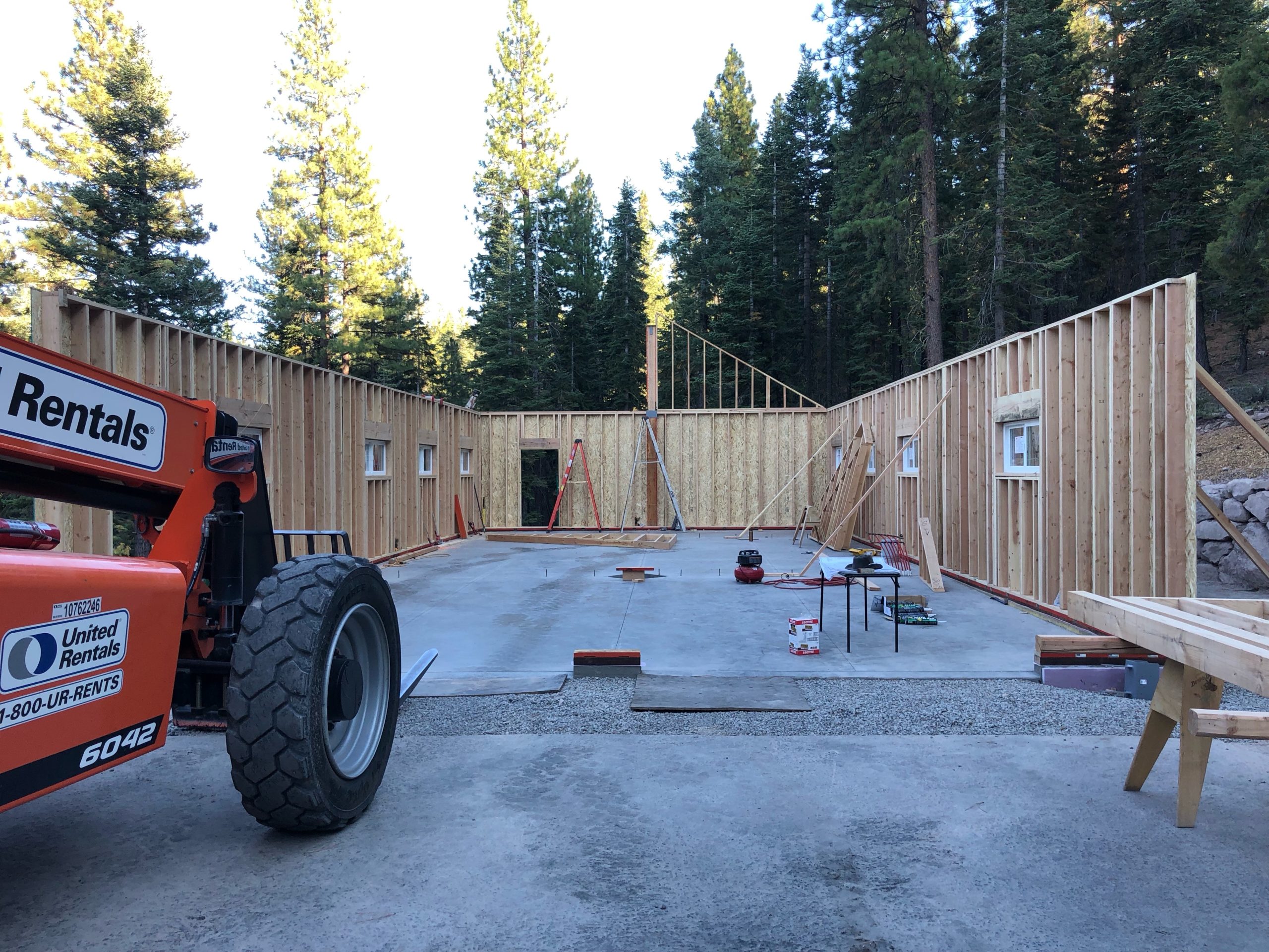
I rented the telehandler for 8 days from United Rentals; it really was essential for raising the walls. The walls came with the exterior sheathing attached, and the windows pre-installed (I’ll talk more about this later…). This made them pretty heavy and not easy to move with manpower alone. With the telehandler, we could add an eye bolt at the top, lift them up with some straps, and drop them into place. None of the guys had driven such a machine before, so I opted to be the driver. The machine is pretty interesting; it had three modes for moving as the front and rear wheels can both turn. The first mode was normal car-like, where turning the steering wheel turned the front wheels as you’d normally expect, with the rear wheels not turning. The second mode was crab-mode; turning the steering wheel would turn both wheels the same direction, allowing you to “crab drive” slightly to the side as you go forward. The last mode was for tight turns; the rear wheels turned opposite the direction of the front wheels. The hydraulics on the machine also allowed it to tilt left and right, which was great for positioning the walls slightly to one side.
There is one thing I want to mention about this “panelized” pre-built wall from Pacific Modern Homes / PMHI. Consider what I’m writing with a grain of salt: I’m not a professional contractor, and this is just my own opinion. I also haven’t ever built any other full size building like this before! So, PMHI utilized a 3-layer bottom plate system, as seen in the following drawing:
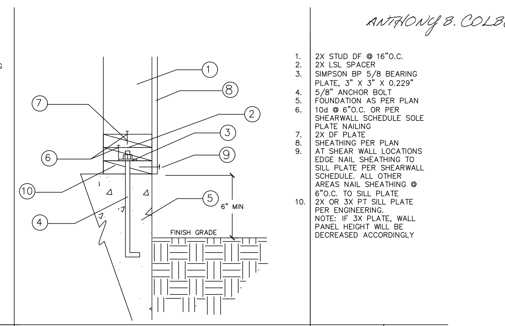
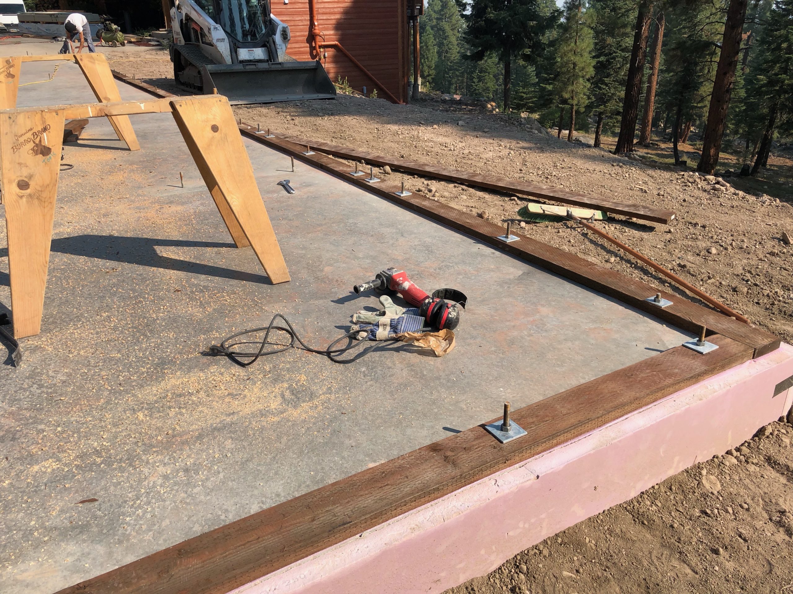
The bottom plate is a normal pressure treated 2x (2×6 in my case). Then there is a 2x LSL spacer and then another 2x Douglas fir bottom plate for a total of three! In normal construction there is just a pressure treated bottom plate, and sometimes there is a double bottom plate. The framing contractor will tell the concrete contractor where to place the anchor bolt hold downs (item #4) so they can avoid poking up where a stud will be; generally they are “soft set” which means the concrete guy will directly place them in the soft concrete and not wire them up before the pour. The framing contractor can then build the walls based on where they want their studs to be, and drill out holes for the anchor bolts in their pressure treated bottom plate. In the case of PMHI they build the walls off-site, and don’t know where the anchor bolts will be. I really wish they would have just specified their specific location on the plans; it would have saved me some headaches and issues, and saved some wood, I think they wanted to avoid the problem of having the studs hit an anchor bolt and require some sort of modification in the field. So, they have the builder lay down a pressure treated 2x as a nailer. They then cut LSL pieces to fit in between the gaps of hold down bolts; you can see this two photos up (the LSL is the wood above the pressure treated wood with the orange side). I’m now sure they used LSL for a specific reason: LSL stands for Laminated Strand Lumber, and it is incredibly dense without the issue of splitting. Some of the pieces of LSL had to be cut really short; like 6″ or less. A normal 2x piece of Douglas fir this small would likely split, but the LSL would not. They may have had some other structural reasons for using it; I don’t know for sure. The three layer plate also caused issues with my hold downs…(more on this later).
Now, I don’t like this triple bottom plate way of doing things. It wastes wood, and required more specialized manufactured wood (LSL) which had to have increased the cost. If you read my first post in this series then you may be aware that I don’t really know how much they charged me for each piece, so it is hard for me to quantify the cost. But I know for sure that three bottom plates are three times the cost of having just one! In addition, it leaves gaps in the wood which need to be filled with some sort of foam insulation, and adds to the cost. Not to mention: wood is not a good insulator. Having a single bottom plate with insulation would be better than having three plates; the wood is going to leak more heat because it has a lower R-value in itself. This could have been solved by wrapping the exterior of the building in foam board…but I didn’t do that.
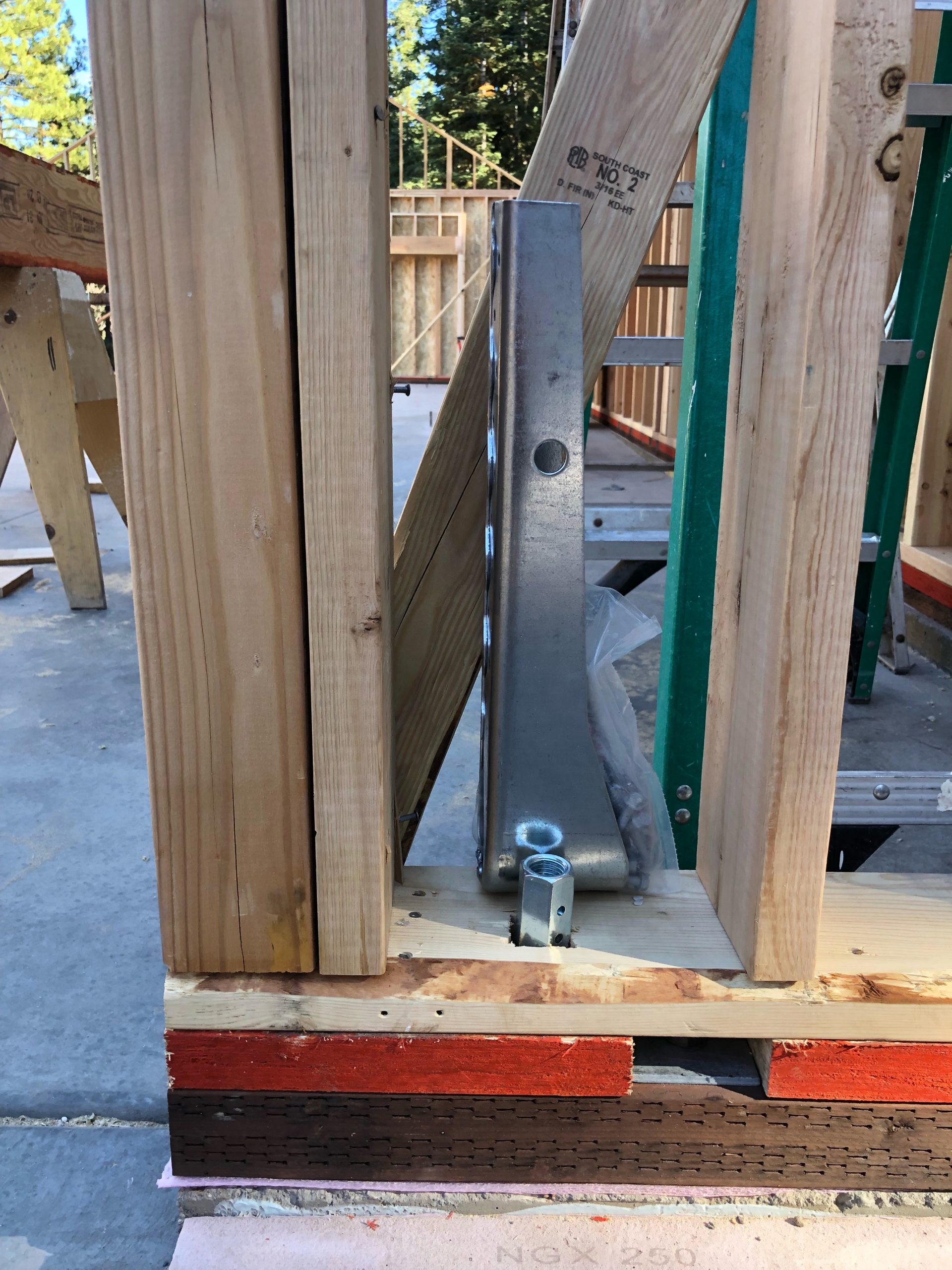
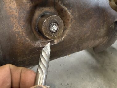
This triple bottom plate created another problem: the shear wall hold downs were too short! Shear walls are really simple: a designated length of the wall that structurally prevents a wall from moving from side to side during high winds and earthquakes. The wall has wood paneling (plywood or OSB) nailed to the outside with a specific distance between each nail based on the required strength. The wall has to be anchored to the concrete with hold downs at each end; these are large metal pieces seen in the above photo. As you can see, the bolt is too short. I wish that CPH/PMHI would have mentioned this to me earlier, as the concrete guys could have used longer bolts. Instead, I had to use a coupling and threaded rod to extend them up, which is perfectly acceptable in terms of strength, but required more cost on my part. It was also stupidly difficult to find the couplings due to COVID supply issues. I drove around quite a bit going to various hardware stores and everywhere seemed to be out.
If you look at the above picture and know construction then you’ll see another problem. The hold down is a good inch and half from the nearest stud. Recall that PMHI pre-made the walls, and my dealer told me where to put the hold downs, but was off along the front wall. The framer usually makes the decision on where to put the hold downs and studs, but when a company off site builds the walls there has to be some coordination to figure out these details. Unfortunately they were off a bit, and the design required the engineers to verify I could stick in another 2×6 and secure it to the much larger 4×6 with a bunch of SDS screws.
In the next post I’ll go over how we got the main ridge beam installed.
If you are just jumping in, check out all the posts on this project in chronological order: The Truckee Workshop Project 2019