LED Cyr wheel: Wiring up the wheel
I have a 5 piece wheel, and I have a “top” side for reference, and the numbers go from one to five in a counter clockwise direction. This is piece 1 to 2, with the 1 insert on the right side. This right side is the location I will push the chips into. The insert can be used to push them in, and usually the insert bolts will only be removed on the right hand side.
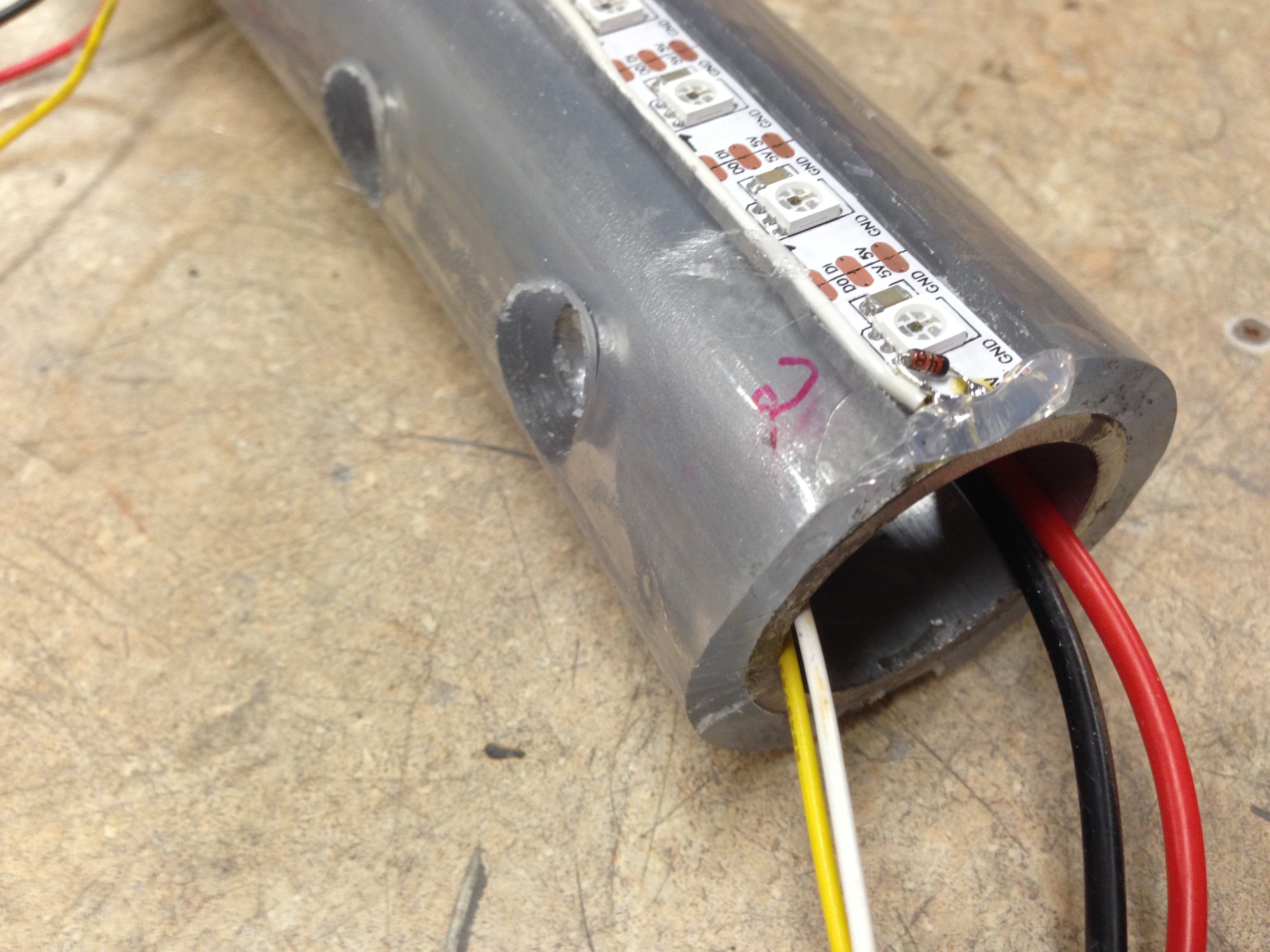
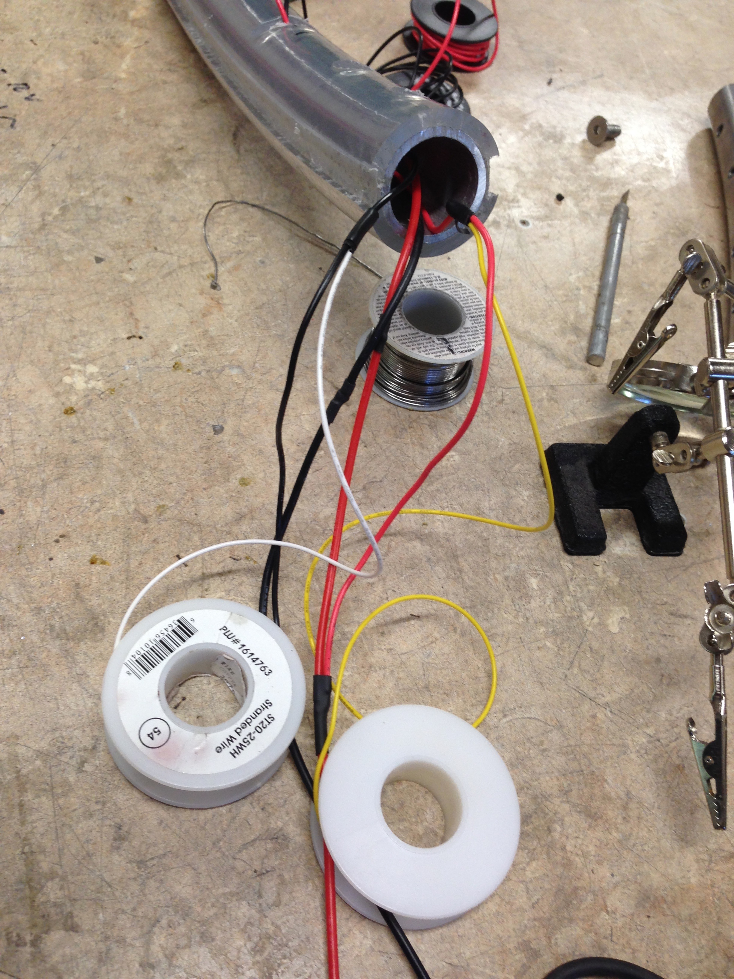
Below: The wires coming out the hole: red/black are 5v. They will be split to power each side of the wheel’s LEDs. The white wire is the data line for one side of the wheel, and the yellow wire is the data line for the other side. They (for now) tie in to the same input on the Teensy, but in the future I could control one half separately from the other if I need to.
Close up of splitting the 5v and ground wire:
The white wire goes to one side of the wheel and the yellow to the other side. I’m only doing one side for now. To the left of the main hole you can see the button; one end of the button goes to a pin on the Teensy, and another to ground. I can then tell when it is pushed and do stuff.
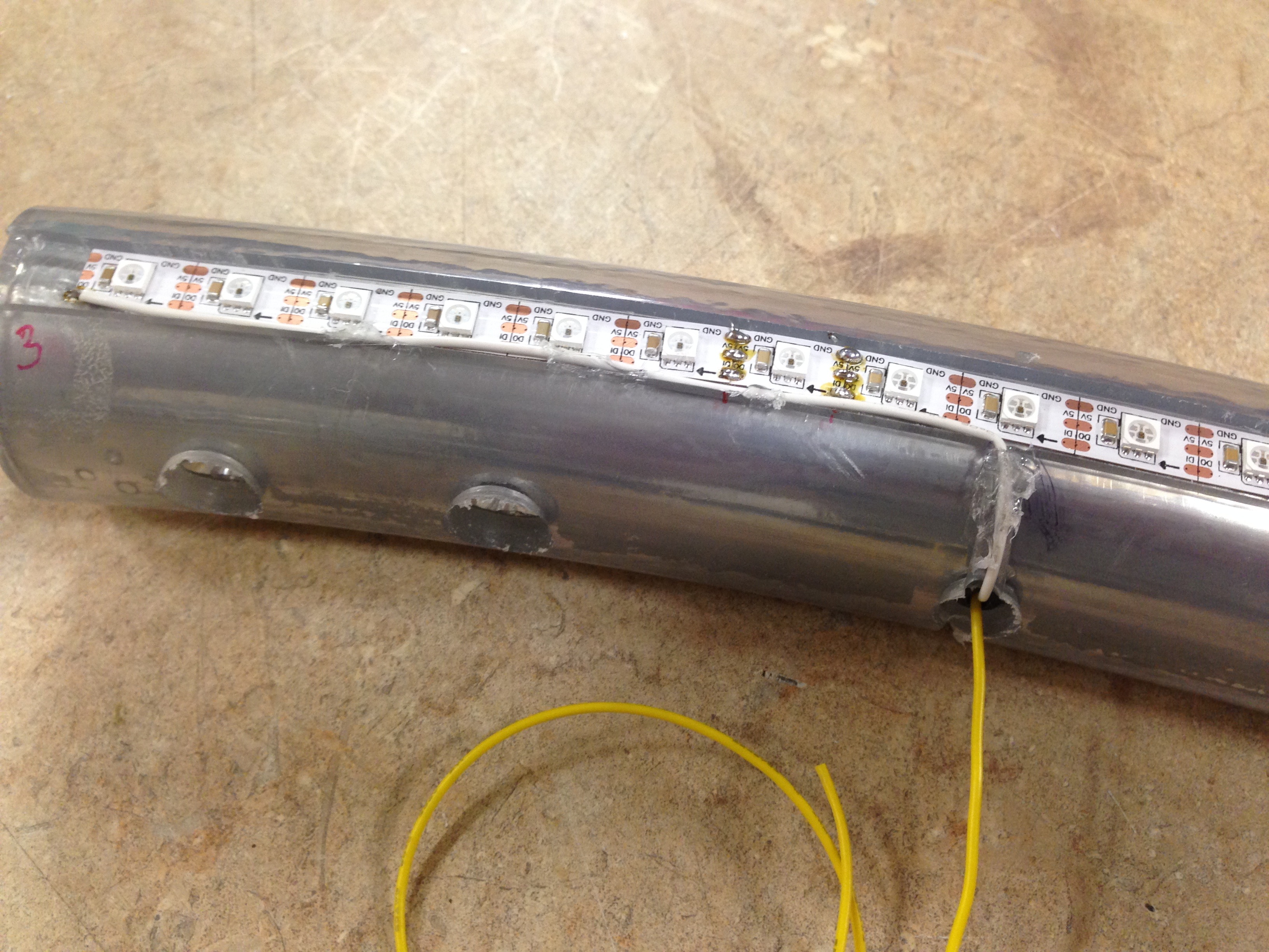
Here’s a close up of the input into the wheel, which has to be far enough down to clear the insert:
The 5v+ and ground can be put anywhere into the strip, but the white data line needs to be on the first pixel (based on the direction of the arrows in the strips). Note that I squeezed in a 1N4148 diode from the DIN (data in) to the +5v red wire (with the negative end of the diode on the +5v); I’m hoping this will help keep the LEDs from dying, because if they do I’m in trouble. The white wire above runs to the DIN of the first pixel, along with another diode:
The other end of the wheel has the DOUT (data out or DO) line that has to feed to the next wheel segment: it runs from back to a hole past the insert:
Again, the yellow is for the other side.
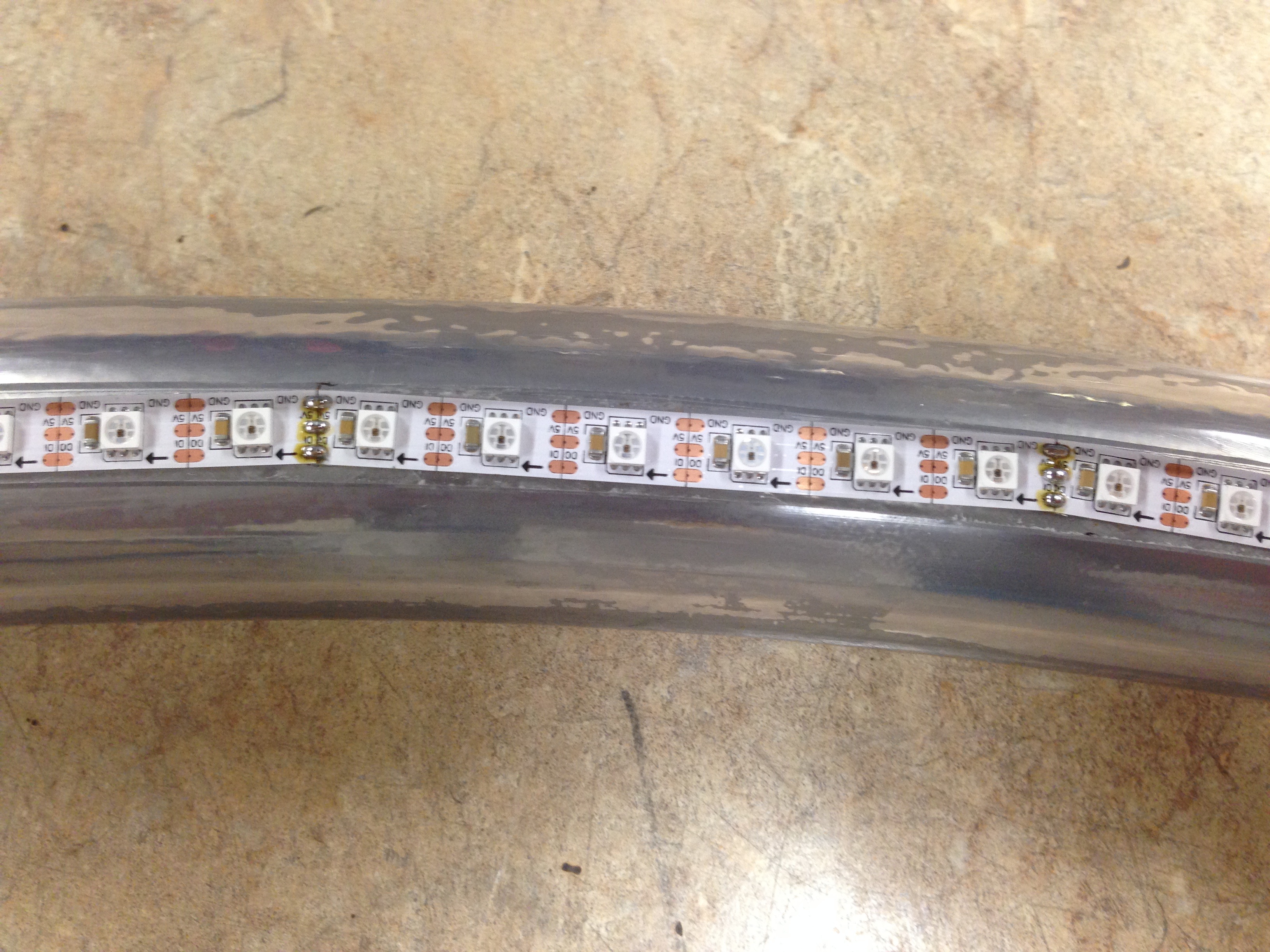
The LEDs themselves half a sticky backing that helps them sit in the groove. Every 6 pixels I cut the DO and 5v line (but not the ground) and tweaked it to match the curve. Then soldered them back together:
Subsequent sections are wired a little differently than the first one. Section 2-3 is below:
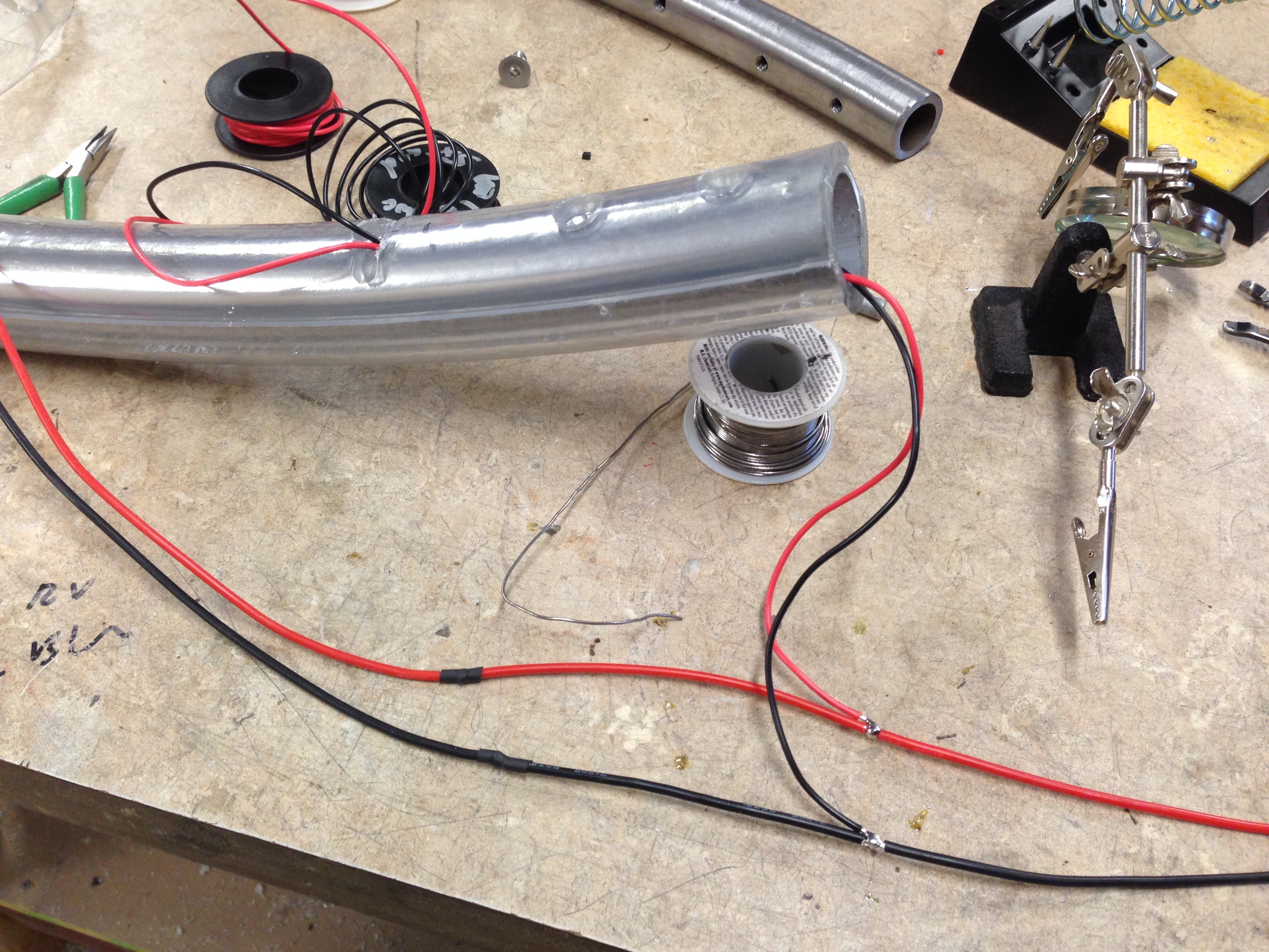
I have a 5v (red) and ground (black) 16 gauge wire going through the entire wheel (minus the last section). I tap off 5v to power each section with 18 gauge wire (note to self: 20 gauge wire would have probably been fine, and use flexible wire for the next one!).
Coming into the section will be the yellow and white data line (used 20 gauge wire; 22 gauge would have been fine since it is just a signal wire — but you don’t want it too thin so it breaks when moving inserts around). In the picture below I’m using the black/red 18 gauge wires to “fish” the yellow and white wires through the hole.
Fished through the hole in section 2-3, and wires getting ready for a connector: