Electric Bug: Charger Control – Design
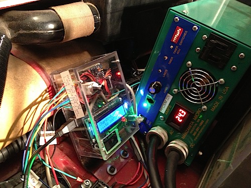
Based on my requirements, I made some hardware the will more intelligently control my Manzanita charger. It is powered by an Arduino, and has a little LCD to tell me what is going on and accept input settings:
First off, everything is on https://github.com/corbinstreehouse/ChargerControl.
It solves the problems I previously listed, by implementing J1772 (minus respecting the amperage that the charging station provides — since I can’t control that in the Manzanita charger) and implements a timer.
I bought an Arduino last winter and learned how to do basic hardware programming.
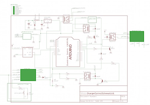
I then used EAGLE PCB software (free) to design how I would do this with some circuitry (after testing it on a breadboard first). The concept is really simple: use resistors to control the J1772 pilot signal, and sense a change in the proximity signal (to detect when the J1772 plug is going to be unplugged), and use several relays to turn on the BMS, turn on the EVSE charging station, and turn on the charger (via its Reg bus input).
The inputs are: 12v power, ground, an AC-DC 12v+ (powered by the 120v or 220v plug so I don’t drain the 12v battery while charging, as my DC-DC isn’t on), pilot signal input, proximity signal input, pilot/proximity ground from the inlet plug, V source output to the BMS (to turn it on), HLIM input from the BMS (to sense when to stop charging via the “high limit” input of the BMS), and a plug into the REG BUS port of the charger to turn it on and off (by connecting pins 1 to 2 via a relay).
The eagle files I made are here. One other thing I added was a diode on the BMS output, as the BMS was accidentally turning my charger control on when the car started.
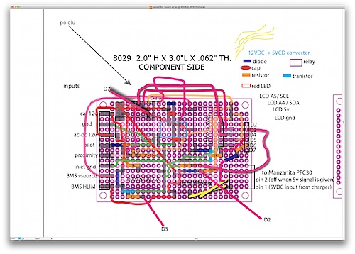
Once I made a schematic, I had to figure out how to get it all onto a board. I didn’t want to print my own PCB (I’m not really at that level yet) so I wired it all up manually. To figure out how to do that, I made this crazy layout in illustrator:
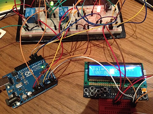
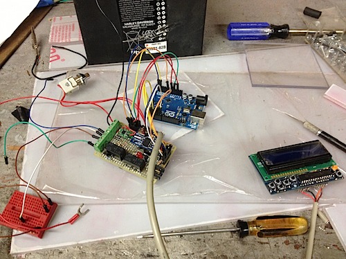
The wiring underneath my board basically ended up looking like this, and it makes me wish I made a PCB. I may eventually do so…when I do some more electronics work on the car. Other parts include a clock kit from adafruit, an LCD kit from adafruit. Here it is all wired up manually to test:
The red mini breadboard is used to simulate the J1772 proximity plug.
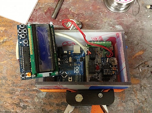
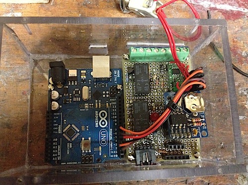
I then made a box out of lexan and stuff everything in:
The on/off switch is a Pololu power switch, which lets me automatically turn the whole thing off in software. See http://www.sparkfun.com/products/8904
Most the important code is here in ChargerControl.cpp. I also wrote an Arduino LCD menu system.
The software works great. I push a pushbutton on top of the box to turn on the whole thing (I could make this automatically happen when the gas tank door opens). Then, plug in the J1772 plug and everything works: first, the the proximity signal on the latch is sensed. Then the Elithion BMS is turned on (via its Vsource input and a relay). The code waits for the BMS to turn “off” the high limit, indicating it is okay to charge. It then generates the pilot signal for the EVSE, which turns on contractors at the charging station and gives the charger power. I then turn the charger on by opening a relay (that opens the charger’s pin 0 to pin 1 connection, indicating it is okay to charge). When the BMS high limit is hit, the relay closes to turn off the charger and it goes into a “balancing mode”. It then “balances” the cells for controllable amount of time, and then automatically (and safely) turns everything off!
When the timer is being used, you just set it to be in “timer mode” and set the start time and duration. The timer EVSE has zero power to the car’s J1772 plug, until the arduino tells it to turn on.
So far, it seems to be working pretty well. I haven’t really used the timer yet and only just tested it.
Warning: use at your own risk.



Hello! bfedfaf interesting bfedfaf site! I’m really like it! Very, very bfedfaf good!
Hello! ggbkeeb interesting ggbkeeb site! I’m really like it! Very, very ggbkeeb good!
[…] Electric Bug: Charger Control – Design […]
Hi Corbin,
You describe the charger transitioning to a balancing mode. What exactly occurs? Does your bms throttle back the charger to low current output by applying a voltage less than 5V to pin 2 of the regbus? Or are you relying on the voltage limit setting of the charger to determine transition from CC to CV, cutback of current, and the charger timer to end charging? What is the charger current output when balancing? What magnitude is the balancing (shunt) current on the elithion?
Hey Tom — it is just connecting the 5V to pin 2 of the regbus. Also, beware of that…as it requires more than 5V to stop charging! Originally, I had the Arduino feeding 5v into pin 2, but that wasn’t working. I then checked the output voltage from the charger’s pin 1 (which is supposed to be 5v), and it measured at like 13v! So, I had to switch to using a relay to connecting pin 1 to pin 2.
My “balancing mode” is just a duration timer; after which, the arduino shuts off the entire system. It does what the charger/BMS normally does at this time: the BMS turns off and on the charger until the cells are balanced (which is defined by parameters in the BMS to be within a certain voltage of each other and above a minimum voltage). The BMS can’t control the current of the Manzanita (which is a shame!), but the charger is usually in CV at that point and is putting out 5-10amps. The amps it puts out depends on the voltage limit set in the charger.
The charger also has a timer, which will stop it from doing any charging at all after a certain timeout — I use this as an extra safety measure in case something else went wrong. Originally the BMS software said to turn off the timer so the BMS could balance cells indefinitely; but that sounded like a bad idea to me.