Corbin's Treehouse - Corbin Dunn, Santa Cruz, CA
Plug Bug
Treehouse
Photography
Videos
Shop
Unicycling
About

Archive for February, 2011

Photography: Protea #2

Friday, February 25th, 2011

Protea #2

Protea2.jpg

Taken at the UCSC Arboretum, Feb 20th, 2011.

Plug Bug: DMV has it registered as an “E”

Wednesday, February 23rd, 2011

In follow up to: http://www.corbinstreehouse.com/blog/2011/02/plug-bug-dmv-process-registering-a-home-built-ev/

I now have the car registered as an EV! I took all the paperwork I had accumulated, in particular the BAR form saying that it didn’t need smog, and the car inspection form I got at visit #2. It took them a while, but they figured out how to enter the right codes in the computer and got it marked as an E for mode of power. I gave them my title, and I should get a new one in two-four weeks. The registration now says “E” on it. Cool!

I really want a carpool sticker. I’m not sure if you can still get them, but I’m going to try with this form:

http://www.dmv.ca.gov/forms/reg/reg1000.pdf

Update: the DMV lady told me the sticker’s weren’t being issued. For PHEV’s (hybrids), she is right. For zero-emission, I think she was wrong. See here: http://www.dmv.ca.gov/pubs/vctop/d11/vc21655_9.htm

I’ll find out in a month or so.

Plug Bug: DMV Process Registering a Home Built EV

Thursday, February 17th, 2011

So, I’ve been trying to register the Plug Bug as a pure EV car. Here has been my adventure so far.

1. First DMV trip. The car was registered non-op, but I drove it down there, thinking that was what I had to do to register it as operable again. It turns out that isn’t the case; they want you to pay first before you drive it at all! I guess that makes sense if I think about it. So, I go to the DMV and tell them I want to register it as an electric car. The lady says I need to get an inspection, so I go out and drive up to get it inspected. The inspector says they don’t do that there. So, I go back in, and the lady says they do…and that the guy was being a grump. So, she pulls some strings and another lady helps me out. She gets on the phone for a while, and talks to people. Finally, she says she’ll inspect the car and we go out to check it out. All is going great, until she needed to see the VIN number. Now, I know where one VIN # is — it is under the rear seat…which is now replaced by a ton of batteries! So, you can’t get to it. She had to see it to verify the car, so she wasn’t going to let me register it as an EV. The only option was to take out batteries (not possible) or get a new VIN (not desired by me). So, I went home thinking that was what I had to do.

Two weeks pass till the next appointment I could get.

2. Second DMV visit. I found the VIN number — it was in the front trunk, and although we had looked at it at the first inspection, it didn’t initially look like a normal VIN but was. She had said she wanted to see 2 VIN numbers…and there was supposed to be a second on the dash (in addition to the one under the seat). I remember seeing a little metal piece on the dash, which I had replaced! So, I went to a hardware store and the owner let me borrow his metal stamps and I stamped the number on a little sheet of aluminum and put it on my dash. So, I go to the DMV the second time, and the guy who is inspecting this time said his son is into EVs and built and raced an electric motorcycle! How cool was that to get this guy? Apparently his son worked at ThunderStruck Motors. Cool! So, he inspected the car, and only needed to see the one VIN # in front, and went inside to double check he was doing everything right. Unfortunately, he came back with bad news, and said that all EVs now need to be inspected by BAR (Bureau of Automative Repair).

Later that day at lunch

3. BAR visit. I got an appointment the same day and drive down at lunch. They say, yes, they do inspections, but as far as they are concerned my car is too old and isn’t “in the system”. So, they don’t do anything to verify it. They recommend going back to the DMV. Doubt!

….I’m now waiting till next week for my next DMV appointment.

Plug Bug: Motor Cooling Ideas and Notes

Thursday, February 17th, 2011

Currently, the car is garaged. It has been wet and rainy, and I don’t have the motor water proofed. I tested making it water proof by using some thick plastic underneath the motor area to keep it dry. I used the stuff that you can buy for under you chair when on carpet — Ace Hardware sells it by the foot. After driving home ~25 miles, I touched the motor, and it was excessively hot! Usually I can keep my hand on the motor; it is warm, but not excessively warm. I do have the motor’s over temp circuit wired to a light on the dashboard, but it didn’t kick on, and I have heard that it will only kick on after the motor has reached too hot of a temperature and caused damage.

So, for me to properly water encase the motor area, I will need some other solution. Maybe some slotted venting or something similar to let it still have airflow.

I’m also considering trying to have it automatically turn on a fan after it reaches a certain temperature. I asked about this on the DIY EV forums: Temperature sensor for a Warp9 to turn on fans. EVSource.com has a nice motor cooling kit that I was already checking out, and I might end up getting it or fabricating something myself in a similar fashion. Jeffrey pointed me to the following interesting parts that might let me do what I want:

34-42C NO Temperature Switch

40A Automotive Relay

Ideally, I want to reuse the blower I have for my heater, and have it swap the exit vent to the exterior of the car when I don’t want the heater on. That would allow me to pre-heat the heater with the motor’s heat, and allow the ceramic heater to work less hard.

The blower I got in the CanEV kit is a SPAL 008-A100-93D 12v, multi-speed squirrel cage. I found the spec here:

http://www.spal.de/_pdfs/en/008-A100-93D.pdf

It looks like it puts out 153 CFM, which is higher than the Jabsco blower sold by EVSource (at 105 CFM) but lower than their Dayton. I’m not too happy with the SPAL blower, as it is a bit noisy, but then again, it is advertised as being “low noise”. I don’t mind the noise as long as I’m driving, but at low speeds I want the car to be dead silent. A few other blowers I found:

http://www.grainger.com/Grainger/DAYTON-DC-Blower-2C646

http://www.surpluscenter.com/item.asp?item=16-930&catname=electric

It would be ideal if I could use my existing blower to go through the motor and then into my heating system. I want a way for it to automatically come on when the temperature reaches a certain point, and automatically go off when it passes past another point. I can do this with a temperature switch that Jeffrey pointed out, or something like this that another EV’er named Brian did on his car: http://s2kev.blogspot.com/2010/09/motor-cooling.html. Brian added a temperature sensor to turn on/off some simple fans. His details on his sensor are here: http://s2kev.blogspot.com/2008/08/motor-temperature-sensor.html — awesome job! I wish I knew more about micro-controllers so I could do something like this. Eventually I’ll learn…

For fabricating a blower-inlet box, I think I will take an approach by this guy here. He fabricated a pretty fancy solution, which I like a lot.

So, while the car is out, I took out the Warp Drive controller and mailed it to Netgain. They are going to fix some issues:

* An error code that seems to have just recently stuck on

* Slight bucking/rocking/hiccuping that happens. Sometimes at low speeds, and a reset of the controller fixes the issue. Sometimes it does it under hard acceleration.

* Update the Interface Module — it is showing *higher* voltage when under load (it should show lower voltage)

I also mailed the Lithiumate BMS back to Evolve Electrics to get the software upgraded. Hopefully it will support the Netgain controller via Canbus.

I repaired the BMS with CL-30 inrush limiters and I’ll test it again when I get the controller and BMS back.

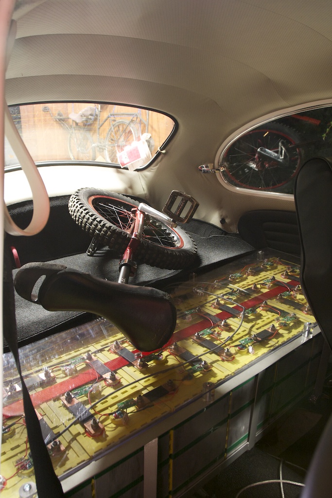
Plug Bug: Unicycle Storage

Monday, February 7th, 2011

I have the rear section finished now and can carry unicycles on top of my cells.

IMG_0647.jpg

Plug Bug: Elithion Lithiumate BMS setup (Part 2)

Monday, February 7th, 2011

… a continuation from part 1.

When putting on the cell boards boards on the cells I was extra careful to not let the wires touch anything or to put the board on backwards. Each board’s LED blinks 3 times when you plug it in. I had two dead boards that didn’t blink when I plugged them in, so I had to get two replacements from Evolve Electrics. One clearly had a bad solder job, but I don’t know what was up with the other one.

Wiring the BMS was pretty much straight forward. Crimping was tough — I bought two crimpers from frys and by using both of them I could get a good crimp. If I were to do it again I probably would try to buy a better one online.

The BMS doesn’t support the Netgain controller yet. Eventually it will limit voltage to the controller when the battery gets low, but for now I wired up the LLIM (low limit) to a 12 volt buzzer.

After the BMS is all wired up, one must do the setup. Here is where I had some confusion. The setup page is pretty sparse and non-specific on what you need to do. In particular, this line

> 1.If the cells are other than LiFePO4, program the cell voltages

I thought Thunder Sky batteries were pretty much LiFePO4, so I incorrectly assumed I should use the BMS values for the LiFePO4, but that was a bad assumption! It would be nice if the setup page said exactly what to do for exactly what brands of cells; that would have made it easier for me. ThunderSky cells are LiFeYPO4 (some Yttrium thrown in) and have a difference chemistry and need a different charge setup. Davide told me on the forum to use.

V-cell-max: 4.0 V

V-cell-high and V-min-balance: 3.5 V

V-cell-low: 3.0 V

V-cell-min: 2.8 V

I’m using a V-cell-max of 3.8 or 3.9 (I forget which one at the moment, as I switched them back and forth), since other recommendations say to not charger higher than 3.8 volts, as there is little to no extra energy in that range. So, my initial charge took a long time; partially because the balance voltage was set too low, and the cells were constantly trying to balance earlier then they should.

Another problem I had was setting the current sensor direction. I’m using only one current sensor for both charge and discharge, and the direction option was confusing me. The arrow should always point into the battery, and if it is you say YES to the setting for current direction (or NO if it points out). I thought the arrow was for the flow of current, so I thought I had to flip the value for one of the two settings. It turns out that wasn’t the case.

The next problem I had was the “State of Health” of the cells was poor — like 52%. It still seems to vary when I charge, especially if the cells shunt excess current for a while, but it is definitely better than before. That seemed to be because the current sensor wasn’t “zeroed out”. More details on this thread.

I’m still getting some other warnings, such as charge over-current. I need to finish looking into those, but they don’t seem to bad.

I also tried using a different 50amp current sensor for charging, but I couldn’t get it to work for some reason, despite having the information and diagram from this thread.

One other important note in testing the BMS. The directions clearly state it, but don’t forget to do a “HOME / Test / Release Outputs” after doing a test operation. I thought setting it back to the original value would be okay — but it isn’t! On my second test charge the voltage of the cells crept up to 4.1 on a cell before I flipped off the charger manually. It took me a minute to realize that the BMS wasn’t turning off the charger because I left the output on. Doubt!

The BMS is pretty cool, although quite complicated. I’m still working out how to get my fuel gauge working. More on that later…(once Jason helps me figure it out!)

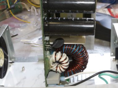
Plug Bug: IOTA DC-DC Converter fix

Monday, February 7th, 2011

UPDATE!

After 100 miles, the solder got so hot that it melted out. I asked the friendly people on EVDL why this would happen. It could be because the inrush limiter was not rated right, or it wasn’t getting enough cooling. So, I replaced it with a CL-30 instead of the CL-40. The CL-30 has a slightly higher amp rating. I also put *another* small fan on top of the inrush limiter to add in cooling. So far, I have ~150 miles and it seems okay.

So, take this posting as-is with no warranty that it will work, or not.

———————

Last Monday I didn’t make it home in the Plug Bug! The 20 amp high voltage fuse for the DC-DC converter had blown, and I quickly discharged the 12 volt accessory battery down with the headlights. The controller then spit out “low 12 volt” errors/warnings and eventually just stopped. I wasn’t sure what to do, so I called my friend Grace Fleming (Nathan Hoover’s wife) and asked if she could pick me up, since she lived close by. She did, and loaned me her car to drive home. I grabbed some tools and then Nathan took me back to my car. I tried to swap the fuse from the heater to the DC-DC converter, as I realized quickly that it had blown. However, it wasn’t keeping the voltage high enough for the 12 volts, but I made it to Nathan’s house. The BMS lots its state of charge (note: that is fixed with a later software rev, which I don’t have), so I was worried I wouldn’t make it home (it said 20%, despite charging at work). So, after a short charge at Nathan’s house, I decided to get a AAA ride home. The next night it ran fine, but I didn’t want to drive it and blow the fuse again.

The kind people on the EVDL list, especially Lee Hart, said that this is a common problem with IOTA DC-DC converters. They are really AC-DC converters, and the capacitors suck in a huge amount of current when it is turned on. That can blow a fuse. The list has a great write up on what to do here: http://www.evdl.org/pages/iotamods.html but it sort of scared me when I read it ages ago, as I am not an EE. I mean, what the heck is a bridge rectifier? I figured I’d just not do those mods, but now I really had to!

Lee told me on the EVDL what to look for, and it was easy to do. At a minimum, I needed to replace the bridge rectifier with an inrush limiter. I ordered this part from digikey.com: KC004L-ND CURRENT LIMITER INRUSH (a CL-40 Inrush Limiter):

IMG_0638.jpg

$17 with tax and shipping for 4 (I only needed two, but like spares), and I got it Friday after ordering it on a Tuesday. I ordered some more fuses from discountfuse.com.

Here’s the converter on the bench:

IMG_0630.jpg

I used general purpose 5 minute epoxy to epoxy these two things down to the board:

IMG_0634.jpg

IMG_0635.jpg

I didn’t replace the capacitors; they are rated for 200V, and I will never see that high a voltage.

I unscrewed the board from the base and isolated the bridge rectifier. It is attached to a heat sink:

IMG_0637.jpg

I had to fight to get it off, as I have never removed anything from a circuit board. After trying to get it loose for a little while, I realized I needed a “solder sucker” and “solder wick”, which I got at frys the next morning. With those tools in hand, the thing came right off:

IMG_0639.jpg

I read on the internet what a bridge rectifier does, and tested the circuit to make sure it was the right part. I also double checked that the part number came up as a rectifier, and sure enough, it did. So, I removed the right thing.

Lee said to consider the 4 holes numbered 1, 2, 3, 4 and to put one limiter in holes 1-2 and another in 3-4. That makes sense, as looking at the circuit on the bottom I can see it passes current through those holes.

IMG_0641.jpg

It was easy to solder it on and put the case back together and so far it is working. I drove 80 miles today. 20 miles to work, charged there, 40 round-trip miles to CAR at lunch, charged again, and then 20 miles home. I think I was at 60% SOC after the 40 mile trip, mostly at freeway speeds: 55-65 MPH, with a few small hills.

Plug Bug: BMS Install

Thursday, February 3rd, 2011

I’ve been driving the car for a few weeks now, and I’m behind on some blog posts about it. The car has a small problem with the DC-DC converter, so I couldn’t drive it this past week (more on that later!).

I purchased the Elithion Lithiumate BMS (Battery Management System). The directions are all located in the online manual, however, some things are not obvious on what to do and it was tricky to set up. In fact, I still don’t have it dialed in quite right, as it is constantly saying I have a poor “State of Health” for the batteries.

Anyways, here is a shot of the BMS modules on top of the cells:

IMG_0589.jpg

I have 48 cells, and I divided my cells into four banks, as recommended here. Bank 0 consists of 5 cells in the rear. Bank 1 is the front trunk pack. Banks 2 and 3 are the rear pack. There are not an equal number of cells in each pack, but that doesn’t matter. The BMS controller module sits behind the rear cells.

There has to be a way to sense the input (charging, or source) current, and the output (discharge, or load) current. A good charger would be able to tell the BMS what current it was outputting, but the Manzanita Micro PFC30 that I’m using doesn’t do that. So, my BMS setup came with this inline current sensor:

2CS00xxL.jpg

The charger has some pretty fat 6 AWG wires, and this inline current sensor is good up to 20 amps, however, the PFC 30 is supposed to take in 30 amps and output up to 40 amps since it is “buck enhanced” (I don’t know what that really means). Splicing in this tiny wire, no matter how short, seemed like a bad idea. So, I asked on the Elithion forums and Davide (the engineer) said I could just use the single 600 amp load current sensor for both readings. It will have up to 1% error in reading the value, and that is 6 amps. That also worried me, but it has been what I’ve been using.

The load current sensor goes around the cable:

201102032223.jpg

and is good for up to 600 amps. I also have another 50 amp one that I will try to use as a source current sensor (however, I couldn’t get it to work correctly yet).

For me, an important page was wiring to the manzanita charger. I decided to do this type of setup, since it is easiest:

charger setup.png

You connect the relay to the HLIM output of the BMS (the High Limit, which indicates the charger to turn off). Now, I wired it slightly differently than what was said in the instructions. Basically, the HLIM input will ground the 12v and turn on the relay, completing the circuit for pins 1-2 on the charger, causing it to turn off. However, the HLIM is normally open, meaning the charger will charge. If the BMS battery source dies (ie: my 12 volt car battery), then it could leave the charger charging! That is bad. So, instead I wired it to the automotive relay’s 87a option, and reversed the HLIM to be normally *closed* when it should charge. This means the BMS holds the relay “on” to allow charging, and if power to the BMS dies it will allow it to open, closing pins 1-2 on the charger and preventing it from charging. I thought this was a clever failsafe solution.

One of the jobs of the BMS is to let me know when the battery is low so I don’t drain the cells to 0 and kill them (which you can do!). Plus, I really don’t want to take the cells to more than 80% “Depth of Discharge”, in order to get more cycles out of them. Hopefully the BMS will eventually interface directly with the Netgain controller and reduce its power output when the battery is low. Until that option is available, I simply wired the LLIM output of the BMS to a buzzer.

I did think of another creative solution on how to reduce power to the controller, yet still let it move the car. The Netgain controller has an input wire that when powered with 12 volts it will reduce the controller voltage. The intent is to allow a “soft reverse”, and I currently have it hooked up to my reverse light. (NOTE: originally I had it hooked up to my taillights, and wondered why power was greatly reduced when the headlights were on!). Another easy way to reduce power when the BMS tells it might be to just wire up the LLIM output to the Netgain controller’s “soft reverse” wire. I will hopefully get around to doing that some day..

…more BMS details later.


(c) 2008-2012 Corbin Dunn

Corbin's Treehouse is powered by WordPress. Made on a Mac.

Subscribe to RSS feeds for entries and comments.

14 queries. 0.297 seconds.