Avid CNC ATC (Automatic Tool Changer) with Mach 4
Last Updated: Feb 14, 2024
Many thanks to Jason Parker of Lamp Light Designs for helping write some of this document, and the original S30C ATC Setup Guide, which helped me figure some things out. Jason also provided a lot of testing and feedback on this software, which I highly appreciate!
If you find this useful, buy one of my digital CNC files from Corbin’s Workshop
I got a 5hp Hiteco QD-1F ATC spindle for my Avid Pro 4896 from CNC Depot. It is similar to the 3hp S30C ATC Spindle package but more powerful and heavier. The QD-1F is also setup similarly to CNC Depot’s new RM series of spindles. Avid CNC’s typically don’t have an ATC, and requires some DIY to set them up. This is my guide on some software I wrote to make setting up the ATC tools way easier without editing any code.
Warning: CNC Machines are dangerous. This is beta code! Your machine could crash and break something, but following my steps will minimize that possibility.
Terminology: A tool pocket is the physical location of the plastic tool fork that holds the ISO30 Tool Holder in a tool rack. This is also sometimes called a Tool Station. The ISO30 Tool Holder is what holds your tool, also known as the bit, but we frequently call the whole thing a Tool. The tool rack is the entire rack of tools in a linear line, unlike a carousel tool rack which is in a circle and not supported. You will have a set amount of Tool Pockets / Stations in the tool rack (numbered from one to X, where X is your number of stations), but you can have an unlimited amount of tools.
Goals [skip reading this if you want]
- Setup UI: Add a user interface to setup tool pockets in a linear tool rack with no coding required.
- Estop: Support e-stop / feed hold during the tool change. I check the error state after each line of code, so an e-stop will stop the tool change within a line or two. This is imperative to prevent “dropping” the tool, as no error checking will continue to run even after an e-stop. This is bad because the draw bar may open and drop your tool. The typical code you will see for tool changes will not be doing any error checking!
- Non-fixed positions: One can map any tool number to a physical tool pocket. Most implementations require Tool 1 to be in Pocket 1. My implementation abstracts it; you can put any tool in any pocket, and you can easily change what tool is in what pocket at any given time.
- Easy Fetching: A way to “fetch” a particular tool, putting back the current one if necessary. Also an easy “Put Back” to put a tool back, or add a new tool to an open pocket.
- Save/Restore State: When a tool change is requested, the code saves the current machine location, travels to a safe z0, does the change, and then returns to the prior position at z0. This is for safety, as some programs (like Vectric VCarve) do a Z-down movement after a tool change before an X/Y movement, which can be disastrous if your table is not clear of stuff, or hit your tool rack.
- Version 6.0 Release: Manual Tool Changes: Support manual tool changes; if a requested tool is not in the ATC rack, or has no position to return to, then the machine will go to the pre-set “Manual Tool Change” location and request the user to do the action (remove the tool or insert the new tool). The user will then hit Continue to continue executing the GCode after the manual change has happened. This doesn’t stop the GCode, so you can’t measure your tools or reset the Z-origin. If you need to do that, you will have to stop the GCode and restart after setting it up the way you want. I don’t use the Avid CNC way of doing the “Manual Tool Change”.
- Fix Avid’s Touch Plate: Avid’s touch plate code will not work if you have a tool height set. This makes it useless for any tool that has a non-zero height. I like to touch off with any given tool in holder, so I fixed it to account for the tool height. This requires my full screen set to work properly, as I have a hook to watch for the dialog to close.
- Cycle Start Check: Whenever a cycle start is hit, I warn the user if the GCode file isn’t on line 0. I accidentally started a cut on a non-zero line..which can be dangerous if the spindle isn’t running. A warning seems very appropriate. It is annoying at certain times, like manual tool changes or resuming Gcode, but I think that is okay for these non-typical operations.
- Fix the Screen Layout: The default layout is terrible. You always want to see the DROs, and sub-tabs would duplicate them. I removed the torch and laser tabs. It’s hard to be good at everything.; don’t use the complete screen if you have either of these, and instead, just copy the ATC and Tool tabs to your Screen.
- Spindle Time Wait: The spindle can start slowing down while the machine moves to the target tool change X/Y position; I use timing to do this, as my ATC spin down time is long.
- Case Pressurization: Most ATC spindles need case pressurization (ie: a constant flow of air) when they are on, and some have a fan. I wanted this to be controllable by Mach 4, so I have a UI option for it on output signal 7.
- Air Pressure Check: Performing a tool change when you forget to have the air compressor on is super bad. It’ll rip the tool out of the fork, and break stuff. I added an easy way to check for air pressure and avoid doing the tool change.
Hardware Installation
For more information on setting up the ATC Hardware, visit this link: ATC Hardware Setup.
Output Signal 6 should be used for the drawbar relay. If you want to change it, it is in Modules/CorbinsWorkshop/ToolChange.lua. If you want a UI option to set the pin, let the know.
Output Signal 7 can optionally be used to turn case pressurization (and/or the spindle fan) on and off when the spindle is running. There is an option in the UI to enable this. If you want to change the pin, it is in Modules/CorbinsWorkshop/CWUtilities.lua. If you want a UI option to set the pin, let the know.
Input Signal 15 is setup to indicate if appropriate Air Pressure is available. This is optional but when enabled allows the Tool Change to not happen if there is not adequate air pressure. This is great in case you forget to turn on your air compressor! The ATC Hardware Setup discusses wiring for this.
Software Installation
*** First install the Avid CNC version of Mach 4. This screen set and code is built on a slightly older version of the Avid CNC release, so some things may not work quite right, so tread carefully! ***
Download the latest Release from GitHub Mach-4-Avid-CNC-Customizations – Click on the latest Release on the right side of the page. Download the Mach4Hobby.zip file; you don’t need the source code.
- Backup Your Existing Mach4Hobby directory. Copying the entire folder to another location is the easiest way to do this, but you really only have to backup your macros folder, as those are the only files that will be overwritten.
- Copy the following into your Mach4Hobby folder:
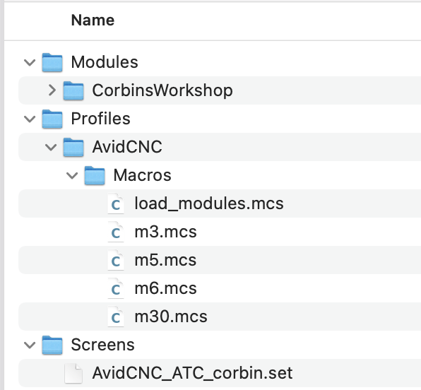
- Put CorbinsWorkshop into your Modules folder.
- Put AvidCNC_ATC_corbin.set into your Screens folder
- Copy the *.mcs files to your Profiles/AvidCNC/Macros folder. This assumes you are using the default AvidCNC profile. If you use another profile, then you should put the files in your machine’s profile location. You might already have customized macros. If you do, then you will need to manually merge the files together. Here is what is changed and why:
- load_modules.mcs – This file loads my CorbinsWorkshop module; if you have already customized it, then you will have to merge the new code in manually. This is required.
- m3.mcs – The GCode M3 call starts the spindle. I added a call to optionally turn on case pressurization and/or a fan, based on a UI setting. You don’t necessarily need this macro.
- m5.mcs – The GCode M5 call stops the spindle. This macro is important. When the spindle is stopped the time is noted for the tool change. A call to ToolChange.lastSpindleStopTime = os.clock() saves the time. This allows the spindle to start slowing down while it is still moving. It also turns off case pressurization, if you have that option turned on.
- m6.mcs – the GCode M6 call is the tool change call; this is delegated to my module.
- m30.mcs – I’m not sure if this is needed, but copy it anyways. It might fix some hangs with the default Avid one due to how the code works.
- IMPORTANT: Delete all the corresponding *.mcc files in your Macros folder. These are the compiled files. Deleting them will force Mach 4 to recompile them from the *.mcs files. You must do this to get Mach to use the new macros. You only have to delete the .mcc files for the corresponding .mcs files listed above.
Start Mach 4 and select File -> Load Screen, and pick AvidCNC_ATC_corbin.set.
The Screen Set has a lot of customizations and is specific to a spindle powered CNC. You can also copy/paste the two ATC tabs to your own screen if you have customized it. Or, you can use my screen set for setting up your ATC pockets, and then go back to using your old screen set. This works fine as long as the custom Macros are still used, but the “Touch Plate” will not work when you have a tool height set.
Mach 4 ESS Input / Output Signal Setup
The only pin setup required is the Spindle Draw Bar. This is covered in the CNC Depot setup manual, but I’ll repeat it here.
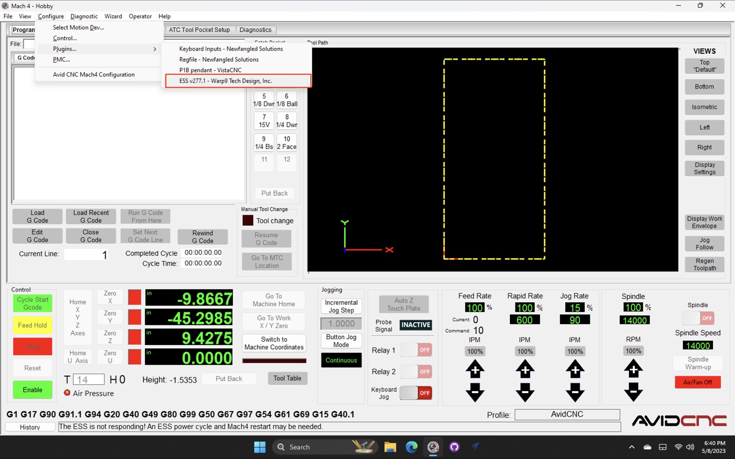
- Start Mach 4 and ensure it is disabled. Bring up the ESS Configuration Panel, by clicking on the menu items: Configure -> Plugins… -> ESS vXXX
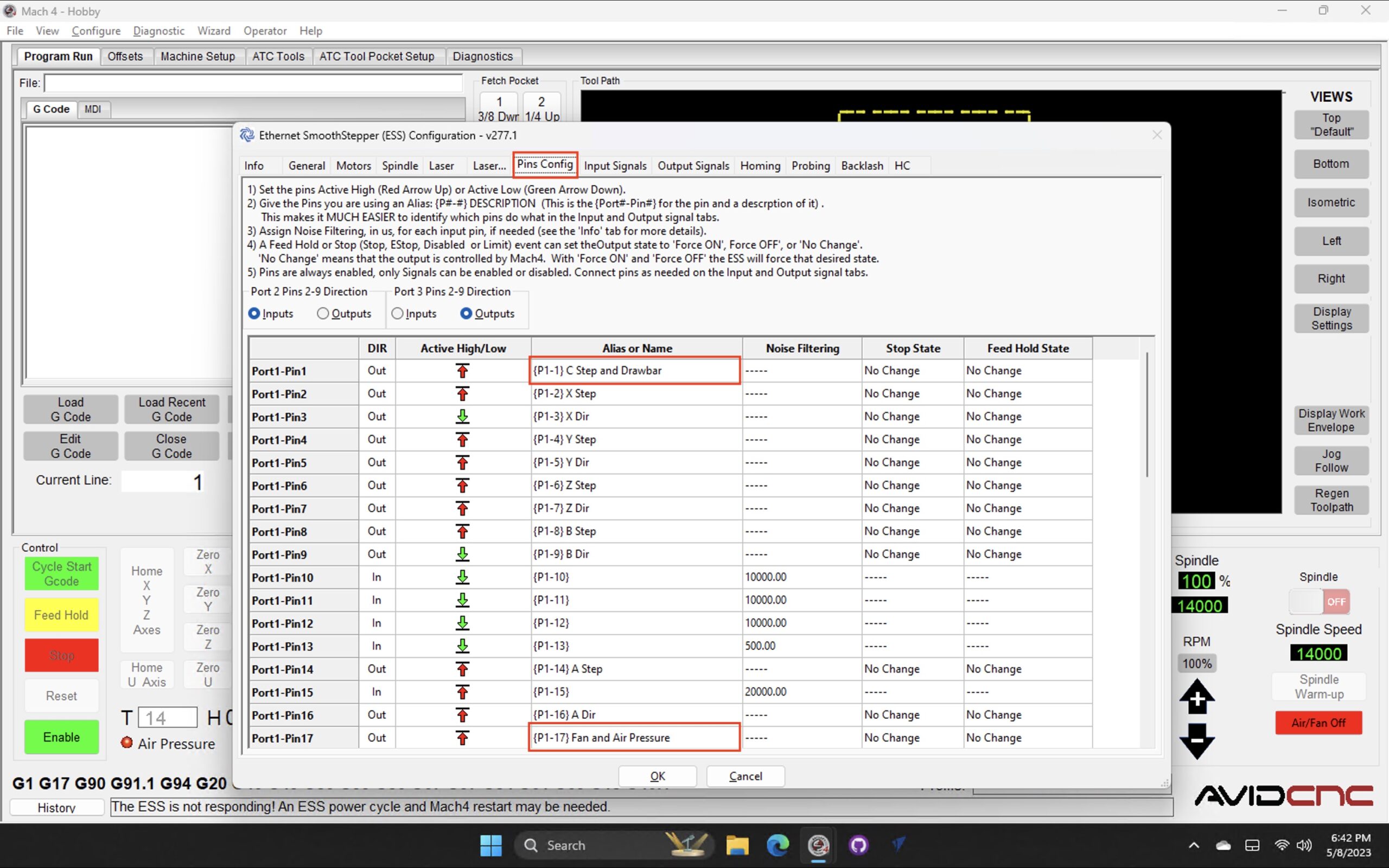
Select the Pins Config tab and rename Port1-Pin1‘s name to be “{P1-1} C Step and Drawbar”. The name isn’t too important, but will be used later.
2. Optional: If you are using Case Pressurization, rename Port1-Pin17 to “{P1-17} Fan and Air Pressure” (this is for Case Pressurization, not the Air Pressure check).
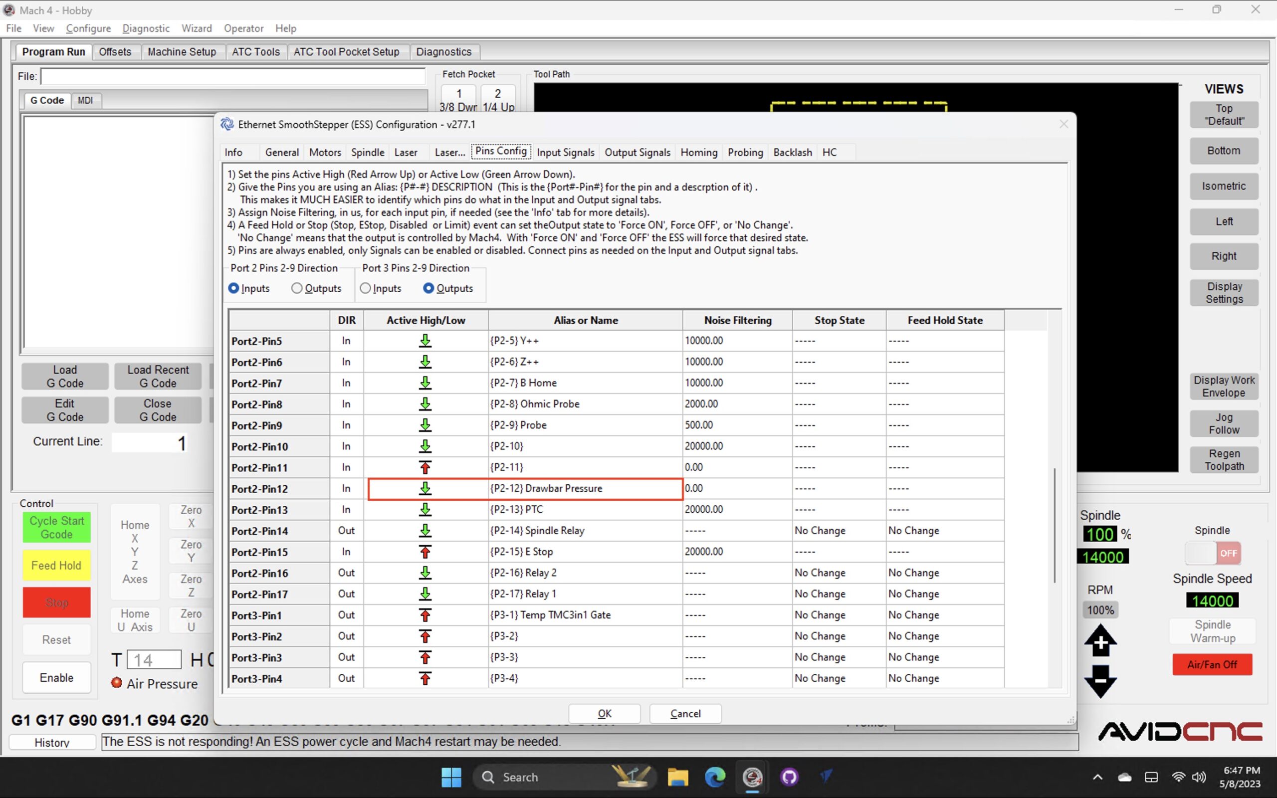
3. Optional: If you want to use the Air Pressure check, rename Port2-Pin12 to {P2-12} Drawbar Pressure. Ensure the Active High/Low is set to the green down arrow (Active Low), and Dir is set to In (the default). Noise Filtering is currently set to 0.00, but I may later recommend setting it to 500.0.
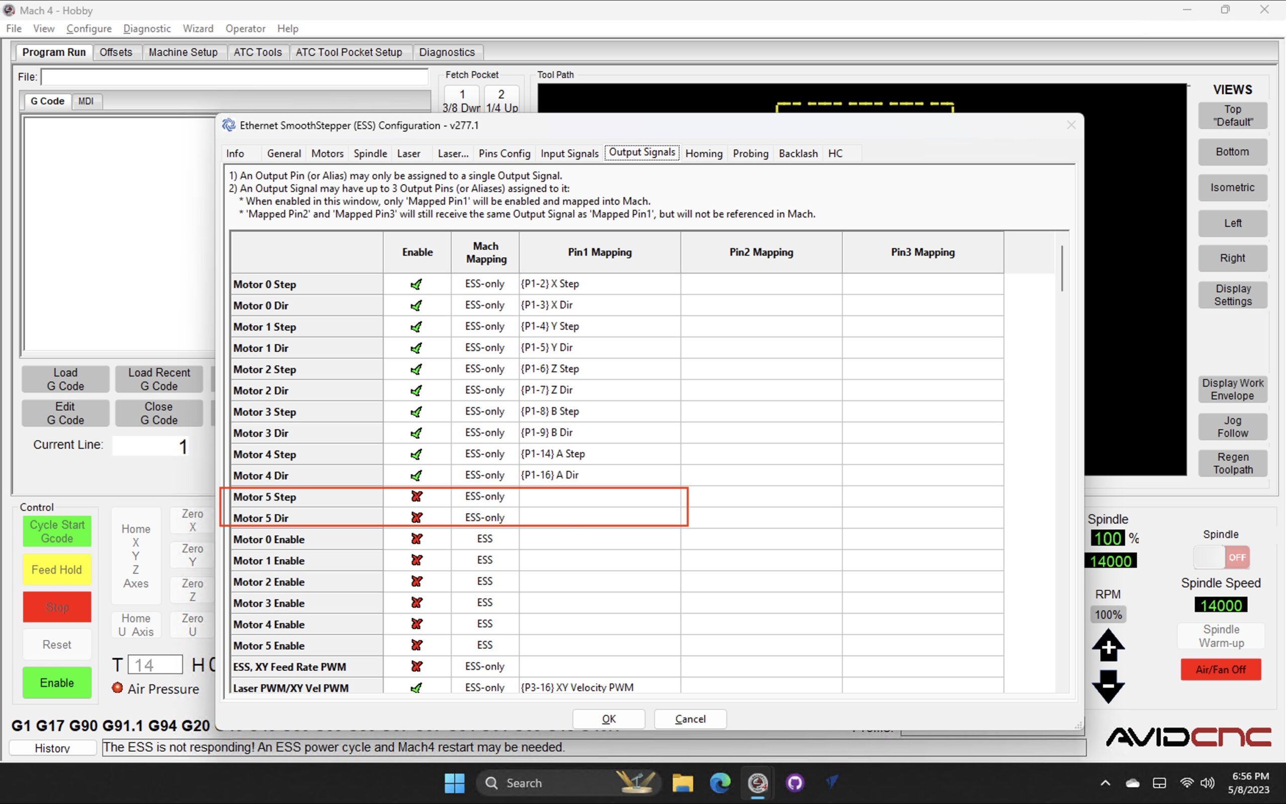
4. Go to the Output Signals tab and ensure that the Motor 5 step signal is disabled and unassigned from the drawbar output signal alias {P1-1} C Step and Drawbar. These signals may only be assigned to one output at a time. So ensure that the drawbar output pin is not assigned to any other output. Do the same for P2-12 Drawbar Pressure alias.
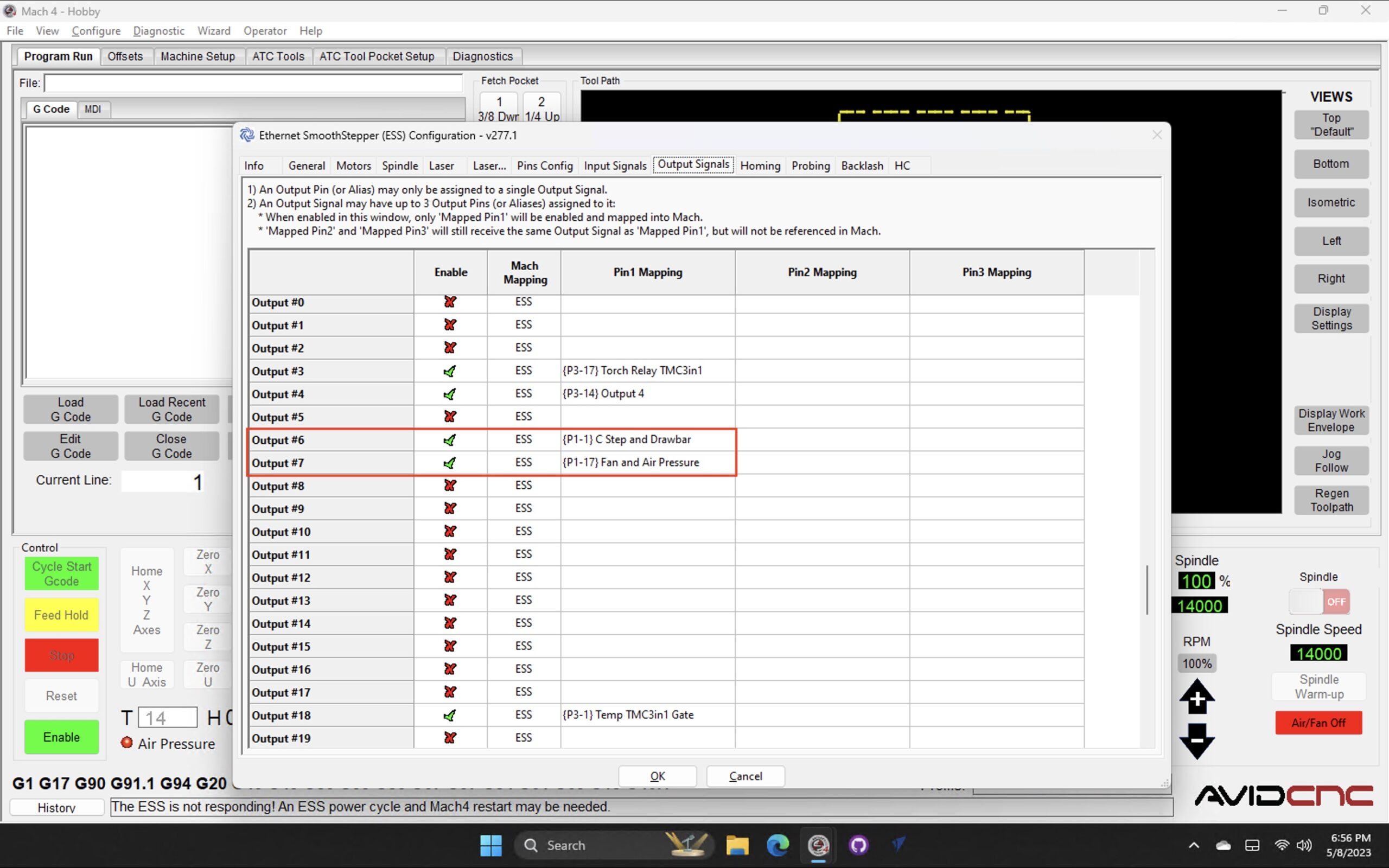
5. Scroll down and assign Output #6 to the alias {P1-1} C Step and Drawbar. Optionally, assign Output #7 to {P1-17} Fan and Air Pressure (This is for Case Pressurization, not the Air Pressure check) . Make sure both are enabled (green check mark).
6. Optional, goto the Input Signals tab and assign assign Input #15 to the {P2-12} Drawbar Pressure alias. This is the optional drawbar pressure check.

Hit OK and restart Mach 4 (important!)
ATC Tool Station / Tool Pocket Setup
Start Mach 4 and open the Screen AvidCNC_ATC_corbin.set, if you haven’t already done so.
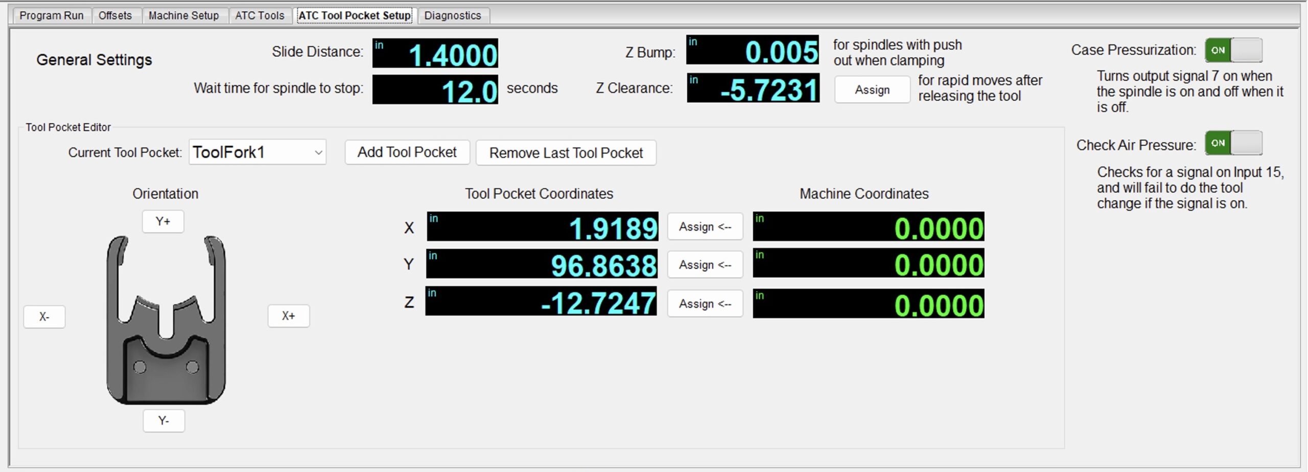
Select the ATC Tool Pocket Setup tab, shown above.
1. Start by adding one tool pocket (tool station), by clicking Add Tool Pocket. Once you add one and setup it’s position, the others you add will be based on this position, which makes setup faster.
2. For the initial pocket:
A. Click on the proper Orientation button that indicates how your “tool fork” is setup. This is based on looking down the machine from the front. This determines the slide direction.
B. Jog to the appropriate X and Y position for the tool fork. See Finding Tool Pocket Positions
C. Click Assign <– to copy the current machine coordinate to the pocket’s coordinate.
D. Jog to the appropriate Z position, and click assign. See Finding Tool Pocket Positions
3. Click Add Tool Pocket to add another tool pocket; it will be automatically selected in the drop down list. The current orientation and position will be copied to this pocket.
4. Generally, just the x or y will vary per pocket. Jog your machine’s x or y to the next pocket position and repeat step 2. You probably don’t need to set the Z again, unless your tool fork heights vary a lot.
5. Repeat for all your tool pockets. They should automatically be saved after each one is added.
6. Slide Distance is how far the slide should happen when getting or removing a tool. This probably needs to be around 1.4-1.6″, but depends on your fork’s size and how large of a bit you use. I tried to minimize the slide distance in order to maximize the usable table area.
7. Z Bump: Some spindles seem to need this, but for me a small distance seemed to be all that needed; or even a value of 0. TODO: Ask others what they set for this and why.
8. Wait time for spindle to stop: My spindle takes 12 seconds to spin down to a stop. It MUST be stopped before the change happens. Time your spindle stop from full speed and set it here. TODO: some spindles can output a signal on the status of the spindle spinning, and it would be nice to read this value and use it in the future.
9. Z Clearance: The ATC change usually uses a safe z height of machine coordinate Z 0. This is the top of the machine. You might want to use a lower value during tool changes to save some time. So, you can set it to your current Z value assuming the ATC will clear the rack with no tool in the spindle. Also make sure it clears the dust boot! This is helpful for people with the 12″ z-axis travel.
10. Case Pressurization: Set this on if you have a relay wired up for case pressurization and/or a fan. See the Hardware Wiring page for more info.
11. Check Air Pressure: Set this to on if you have this wired up and working correctly.
All the parameters are saved to a new file at Profiles/AvidCNC/ToolTables/ToolForks.tls. It is an ini file, and should be easy to read and modify by hand. It is read each time a tool change happens, and each time the ATC tab is opened.
Finding Tool Pocket Positions / Tool Stations
This is based on Jason Parker’s Guide. Thanks Jason!
First, ensure your machine is homed! Set your jog speed to something slow, and take it easy to avoid crashes. If you don’t have a laptop, then use a pendant to jog your machine, or a wireless keyboard.
Finding the tool station locations is not difficult. There are two methods of finding the tool fork locations. Method 1 is more precise but takes more time and has more steps to the process. While method 2 is faster but not as precise. However, method 2 arrives at a similar result. Both processes will be described and the steps outline for both. Choose what is best for the system and the level of precision desired.
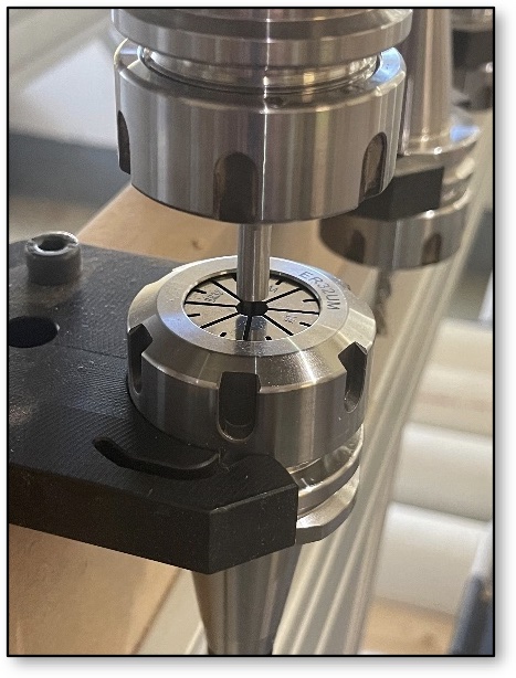
Method 1: Double Tool Holder Higher Precision (Figure 25)
This requires two tool holders, both with the same size collets. Tool holder one will have a precision steel dowel installed and be loaded into the spindle. You can also use an upside down bit. Tool holder two will have a loose collet and is placed upside down in the tool station fork. The spindle is jogged over to the inverted tool holder and the dowel is jogged down into the collet. This finds the X/Y plane values for the station. The Z value is found by driving the tool holder into the fork after the inverted holder is removed from the station. This method gives a much more precise X/Y value. This means there is less potential for damage from the tool holder taped rubbing or scratching the inside walls of the spindle when either lowering or lifting during tool exchanges.
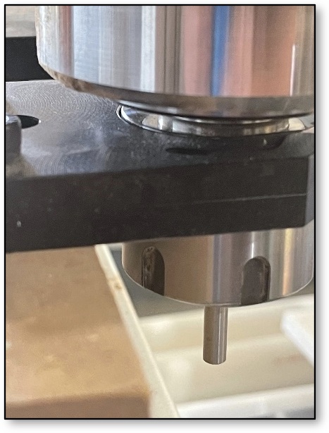
Method 2: Single Tool Holder Lower Precision (Figure 26)
This method is faster than method 1 and arguably less precise, however, the results can be good if care and attention to detail are taken while executing the process. The method uses a single empty tool holder installed into the spindle. Carefully drive the holder into the fork paying attention to the deflection of the two arms of the fork. The arms should deflect outward at the same time and distance. Jog the tool holder into the fork until it is fully rested in the folk. While the tool holder is parked in the fork, the X, Y, and Z values can be found.
Method 2 is considered less precise than method 1 because the tool holder could be under or overdriven into the holder in X, Y, and/or Z. When the drawbar is then released, the fork will exert a force to center the holder in the fork. When the spindle raises or lowers this difference could scratch the taper inside the spindle or on the tool holder, neither is desirable on precision machined surfaces. Additionally, if misaligned going in or out of the fork it could damage the fork or cause the fork to not hold the tool correctly causing it to fall possibly damaging a tool.
Method 1: Double Tool Holder Higher Precision
Below is an outline of the process for using the double tool holder method of finding fork locations. This is a step-by-step process.
- Home the machine
- Setup
- Tool holder 1
- Install precision steel dowel (or inverted endmill) into tool holder, allow a minimum of 0.75” (19mm) stick-out from the collet
- Install tool holder into the spindle
- Tool holder 2
- Install the same sized collet as tool holder 1. When installing the collet nut, it should hold the collet such that the steel dowel slides into the collet with light friction
- Install holder in the station fork with the collet facing the spindle
- Tool holder 1
- Process
- Set the Z to a safe distance above the inverted collet in the tool fork
- Jog roughly over the tool holder
- Slowly Z down toward the collet empty collet of the inverted holder
- Make X, Y, and Z adjustments until the steel dowel in the tool slides into the empty collet of the tool holder 2. Watch for any deflection of tool holder 2, this indicates the holders are not aligned and more adjustments are needed.
- Once aligned, click the <– Assign button to assign the X and Y position for this pocket.
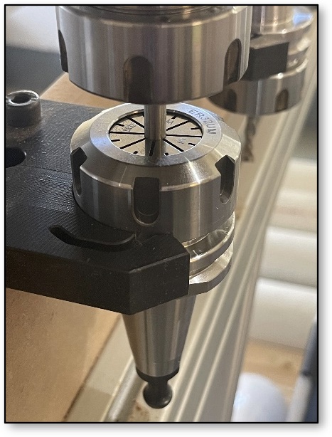
- Raise the Z to clear the dowel from holder 2
- Remove tool holder 2 from the fork
- Jog in the direction of the fork opening such that the tool holder can be safely lowered and slid into the fork (do not use the Z at this time)
- Try and jog only in the one axis to move in front of the fork opening.
- Lower the Z until the groove of the tool holder is aligned with the lip in the center of the tool station fork. The flat at the bottom of the ISO30 taper should align with the top surface of the tool station fork.
- Adjust only the Z and the axis needed to slide the tool holder into the station fork.
- The X and Y values should match those found in part 4e of this section.
- If the tool holder appears fully seated, click the <– Assign button for the Z value on the pocket.
- Jog the tool holder out and clear of the fork.
- Install tool holder 2 into the next station and repeat for the next pocket position.
Method 2: Single Tool Holder Lower Precision
Below is an outline of the process for using a single tool holder to locate the tool station fork locations. This is a step-by-step process.
- Home the machine
- Setup
- Install an empty tool holder into the spindle
- Decrease the jog rate to a very slow rate. The tool holder is going to be jogged directly into the holder so a slow jog rate will increase the precision and decrease the cause of damage in the event the tool is jogged in the incorrect direction.
- Process
- Lower the Z to approximately level with the tool station fork
- Jog roughly to the first station fork opening
- The flat at the bottom of the tool holder taper should be roughly on the same plane as the tool station fork top surface
- Carefully jog the spindle to move the tool holder into the fork
- Adjust the X and Y such that when the tool holder moves into the fork both arms deflect at the same time and for the same amount.
- Adjust the Z to ensure the lip at the center of the fork slides into the groove in the tool holder and that the flat at the bottom of the tool holder at the bottom of the taper is level with the top surface of the tool station fork. See figure 25.
- Continue to jog the took into the fork opening until the holder is fully seated in the fork, this is slightly subjective. Do not overdrive or underdrive the tool holder into the fork as doing so will cause the tool holder to shift in the fork when the spindle releases it. Misalignment has the potential to damage the tool holder taper or mating surface inside the spindle during a tool change process. Misalignment may also cause premature wear of the tool holder, spindle, and/or tool station forks.
- Once the tool holder is seated correctly in the fork, click the <– Assign button for the X, Y and Z position of the tool pocket.
- Carefully jog the holder out of the station fork
- Repeat for all the pockets
ATC Tools Setup
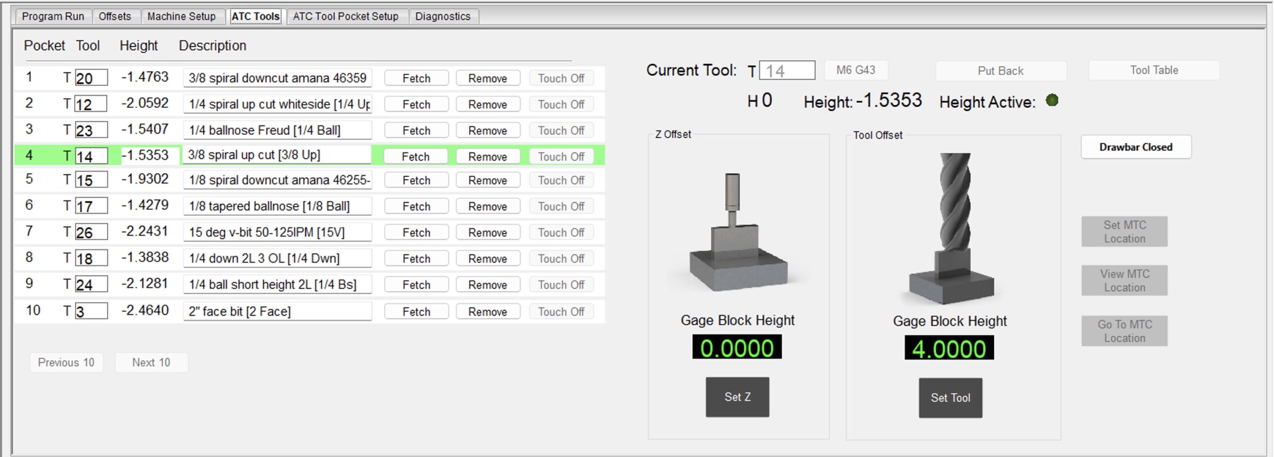
This tab sets up the mapping from a particular tool pocket/station to a tool number — the actual bit.
There should be a row for each pocket you previously setup. To set a tool in a particular pocket, simply type the tool number in the Tool Column and hit enter. Tool 0 is a special tool that can not be used in Mach 4, and simply means “empty”. If you have more than 10 pockets, you can use the Previous 10 and Next 10 buttons to scroll through all your pockets.
The tool’s Height will show up, along with the Description. You can edit the Description inline, and it will update ether value in the Tool Table. Note that I name my tools with a part in brackets, ie: “3/8 spiral up cut [3/8 Up]”. The part in the brackets, “3/8 Up” will be used for the button label on the main page, which is described below.
Green background: This is the current tool in the spindle.
Fetch Button: This will do a tool change, putting the current tool back in it’s pocket, and fetching the requested tool.
Remove Button: This removes the tool from this pocket. No movement will happen on the machine. It is the equivalent of overwriting the tool with Tool 0.
Touch Off Button: Not implemented yet. The idea is to automatically touch off the tool on a fixed tool height setter, which is useful when adding new tools. TODO: Hide this until I implement it.
The area on the top right:

This shows the current tool in the spindle, which may or may not have a pocket/station. The edit box to the right of T allows you to manually change the current tool. Simply type in the tool number and hit enter; this will perform a manual M6 G43. The machine will not move. The tool will be set as the active tool, and it’s height will be activated. In the above screen shot, the tool height is NOT active, the green dot is not active, and H 0 means no height is active. This happens when initially starting Mach 4, as it will not restore the tool height as active. Type 23 and hit enter to activate it. You can input any tool number here; it doesn’t have to be a tool in your tool rack.
Put Back Button: Saves the current X/Y coordinate, puts the current tool back in a pocket (if assigned), and comes back to the current X/Y coordinate. The machine will move.
Tool Table Button: Brings up the standard Mach 4 Tool Table, also available from the menu item.
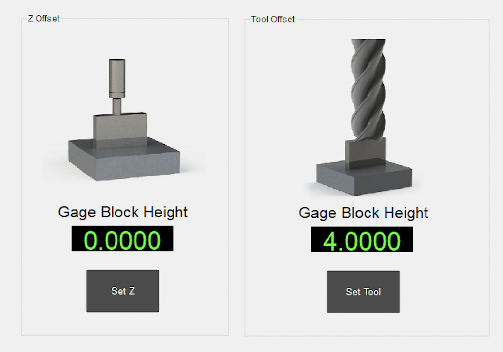
The Z Offset section, was copied from Mach 4’s default screen. It allows you zero out the current Z using whatever is in the spindle. TODO: check to see if this works with tool heights assigned
The Tool Offset section allows you to set tool heights for the active tool based on a gage block.
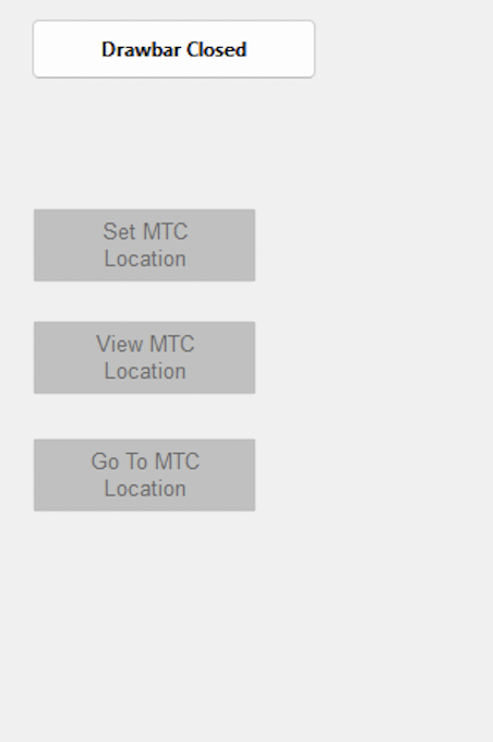
The Drawbar Open/Closed button is hardcoded for Signal Output 6 and will activate it when clicked (IE: open or close the drawbar). It is the same as the button from CNC Depot’s screen. The code does no checks on the spindle being active, so use at your own caution! This button was removed from the main screen, as it is dangerous to have an “open drawbar” button right next to a button to stop the spindle rotation. Accidentally hitting the button when the spindle is on could cause the tool to fly out.
The last three buttons are copied from Avid’s default screen set, and are for setting the Manual Tool Change (MTC) location. I need to rework how the manual tool change logic works a bit to make it easier.
Simply put your tools into a tool pocket and assign that tool number in the UI for each pocket.
Main Page User Interface
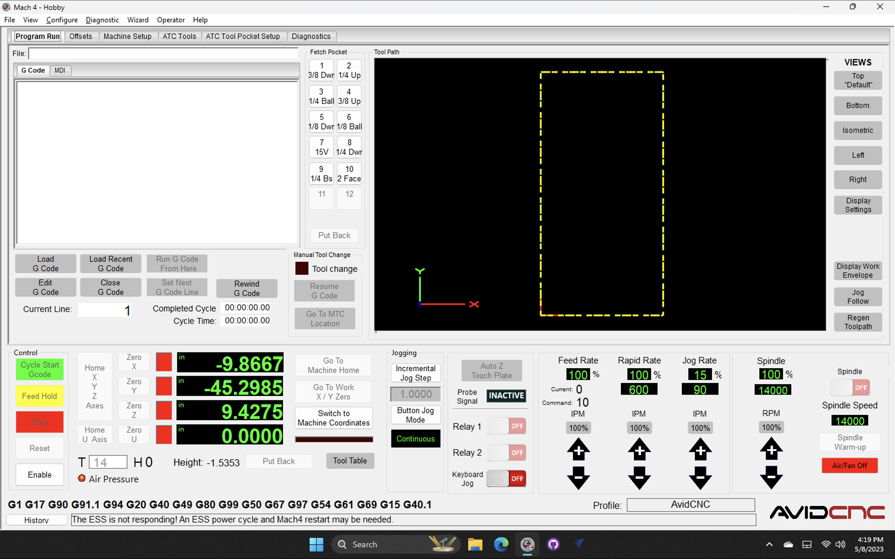
I modified the main User Interface (UI) to be more friendly for an ATC with only a spindle. I removed all bits related to Laser and Torch control. If you use a Laser or Torch, you can still use this Screen Set to setup the ATC Tool Pockets, and then go back to using your familiar old screen set.
It is important to always see the DROs, so I moved them to always be visible. I also consolidated all GCode related things into one tab.
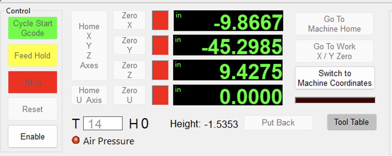
The first thing you do after hitting “Enable” is login to be “Home” so those buttons are close to each other. The “T [14] H0” field is the current tool and tool height. Tool 14 is active and Height 0 is active, which means no height is active. Whenever Mach4 starts it remembers the last tool, but the height is not set. This is important to note, in case you use the touch plate with a bit installed!
You can type any tool number into the Tool field after the machine is enabled and hit enter. That will make that tool active and assume you manually put it into the spindle, assuming you manually removed the prior tool, if any. It also activates the tool height for that tool number, so H XXX will show the active height, and the actual value for the tool is shown to the right.
The Put Back button puts the tool back into pocket that it is assigned, leaving the spindle empty with no tool. It will return to the starting position after putting the tool back. TODO: Put Back will put the current tool into any available empty pocket and assign it to that pocket. If the tool does not have a pocket, and there are no empty pockets available, Put Back will do nothing. TODO: Disable it when it can’t do anything.
The Air Pressure LED light will be green when you have active air pressure. See the hardware setup how on how to wire it up and make it work.
The Tool Table button just invokes the Mach 4 tool table for editing.
The Goto Work Home button goes to The X/Y/Z 0 of the machine but backs it off a little bit. I hit this button before turning off the machine to make homing faster when I turn it back on. It goes to Z 0 first to ensure it doesn’t hit anything and then rapids to the X/Y.
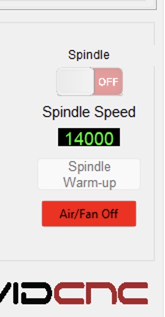
On the right is another new button labeled Air/Fan Off. This is tied to the optional Output Signal 7 to turn on/off Case Pressurization and/or the fan if you are using a HITECO Spindle. If you don’t use this, you can edit the screen and delete the button.
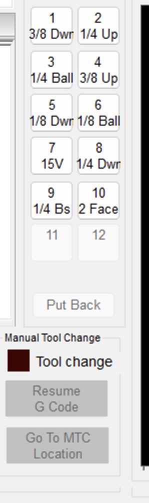
In the middle of the screen are some “Fetch” buttons for pockets 1 to 12 and a Put Back button. I may remove the Put Back button, as it is duplicated below. The “Fetch” buttons will fetch the tool in the pocket that you click on. Only up to 12 are available due to UI space. If another tool is already in the spindle, it will be put back before fetching the requested tool. The tool height will also be set; it invokes the M6 code.
The button labels are dynamic based on the tool assigned to the pocket. The first 5 characters of the “tool name” setup in the tool table is used. OR if your tool name has some part surrounded in brackets, it will use that for the button table. For example, if your tool name is:
3/8" Spiral Downcut Amana xx333 [3/8 Dwn]
The string “3/8 Dwn” will be used for the label. If you don’t have anything in brackets, then the first 5 characters will be used.
Initial Testing
Once you have setup all your tool mappings completed, get ready to test a tool change. Follow these steps to ensure the machine will safely perform tool changes. Keep the e-stop button handy! NOTE: Hitting the e-stop before the spindle is about to open might drop your tool! Be careful.
- For the initial test, remove all the tools from the pockets/station, and from the spindle (it should be empty). Remove your dust boot.
- Ensure your Active Tool is Tool 0 (which is “no tool in the spindle”)
- Ensure your machine is homed.
- Set the machine Rapid Rate to 25%, so the moves will be slow. Go slower if you want to be more careful!
- On the ATC Tools tab click the Fetch button for the Pocket 1 row.
- You should get a warning to ensure the spindle is empty; click OK
- The machine spindle should move up to Z 0 (the top)
- Then it will rapid (at 25%) to the X / Y position
- You should hear the drawbar open
- The Z will go down to the Z pickup height
- You should hear the drawbar close
- The “slide” will happen to pull the tool out of the holder
- The Z should go back up to the Z 0 position
- The machine will rapid (at 25%) to the original X / Y position
- The Active Tool should be the tool that you had in pocket 1.
- It is important to make sure everything looks right. Ensure the X / Y position was right, ensure the Z heights look right, and importantly: ensure the slide direction to pull the tool out was in the right direction. Ensure the Tool is active, and the height is active.
- Still, with no Tools actually installed. Click the Fetch button for Pocket 2’s row.
- This will “Put Back” the first tool:
- The machine will go to Z0
- Rapid to the pocket’s X/Y, plus the slide amount
- Rapid to the pocket’s Z position
- Slide in
- Open the drawbar (you should hear it)
- Lift up to the Z Clearance Height (keeping the drawbar open all the time)
- Rapid to the next pocket’s X/Y and repeat Step 5’s operations.
- This will “Put Back” the first tool:
- Repeat Step 8 for all your pocket positions.
- In the Current Tool text field, type 0 and hit enter. This means you “removed the tool”.
- Now put your actual tool holders in each pocket.
- Repeat steps 5 and 7 with your actual tools.
If you encounter an error, click on the History button in the lower left and see what it says.
The tool rack should now all be setup and working correctly.
Setting Tool Heights
I have a video showing how to do this: Setting ATC Tool Heights in Mach 4
Post Processor Setup
You must setup the post processor to generate tool changes. I wrote it on a separate page:
Avid CNC ATC Post Processor Setup – Vectric VCarve and Aspire
Manual Tool Changes
In Release 6.0 I added better support for “manual” tool changes when a tool isn’t available in your rack. Assign the “Manual Tool Change” location using the UI buttons to wherever you want on your CNC table. The X/Y and Z location is saved, but only the X/Y position is used, and all movements happen at the machine Z zero location (the top) for safety.
When a tool change is requested for a tool not in the rack, the machine will go to this location and prompt the user for a tool change. After the user does the change, they can hit Continue to continue executing the GCode. You can hit Cancel to stop the GCode if something is wrong (like the tool needs the height set in the Tool Table).
Note that I haven’t tested this very well yet, so use it carefully the first few times.
Change History
Dec 31, 2023: Minor updates
Aug 24, 2023: Updates
Feb 14, 2024: Added notes about the manual tool change support for release 6.0.