How to Setup an Automatic Tool Changer (ATC) on an Avid CNC
Video link: ATC Setup on Avid CNC
This is a companion article for the above video where I talk about setting up an Automatic Tool Changer (ATC) on a CNC machine.
For the Mach 4 software side of things, visit: Avid CNC ATC with Mach 4
Spindle Options
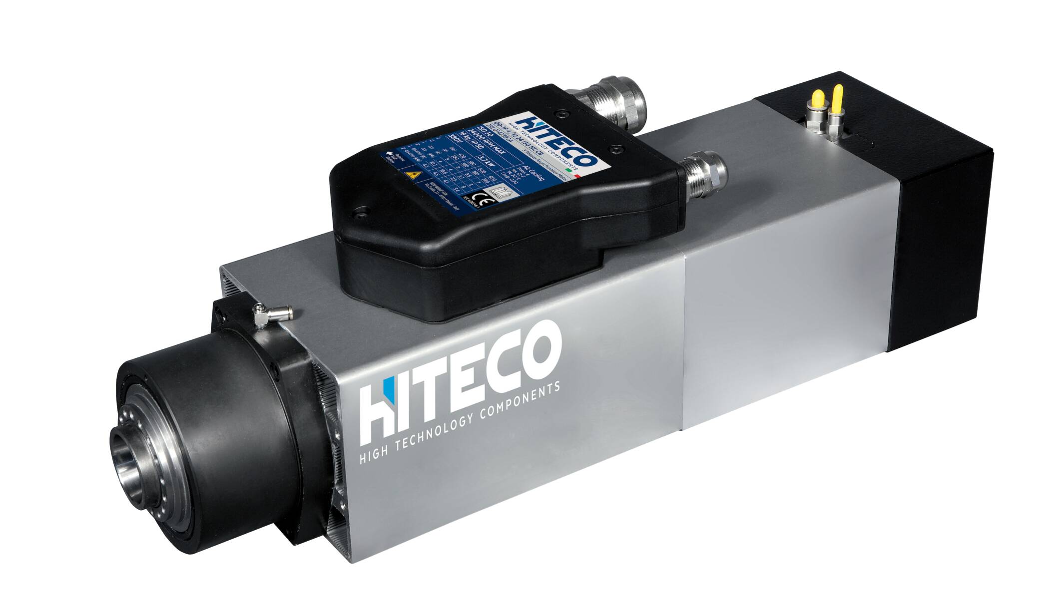
I purchased a HITECO QD-1F spindle and the Avid Spindle Control Box from CNC Depot, along with 6 tool holders and tool forks. This spindle puts out about 5 hp with the paired VFD — or so I hope. The actual VFD I was given says it is good for 3HP on single phase, but Alex from CNC Depot assured me that the manufacturer said it can do 5 HP. I’ve accidentally done a 1.25″ full depth cut at around 60 IPM in hard maple with a 1/4″ downcut bit, and it didn’t break. That is pretty amazing!
However, I really think I don’t need 5 HP, and CNC Depot’s 3HP S30C spindle kit would have also been a great choice for me. Update: Sept 2023: CNC Depot now offers a 4 HP and a 7 HP ATC spindle! Check out their products page. If I were to do it again, I would probably get the 7HP one from CNC Depot; I have a feeling it is lighter than the HITECO (but I don’t know for sure as I can’t verify the weight). It also has a fan; which was one of the issues with the S30 series of spindles — they ran really hot without a fan. If you get a CNC Depot RM30, RM40 or RM70, you can set it up like the Hiteco.
Air Setup
The power drawbar in an ATC requires air pressure to operate. The HITECO and S30C need around 105 psi. I have a relatively-cheap Home Depot air compressor that works fine for this. The hard part is getting the air dry to ensure you don’t get any water in your spindle.
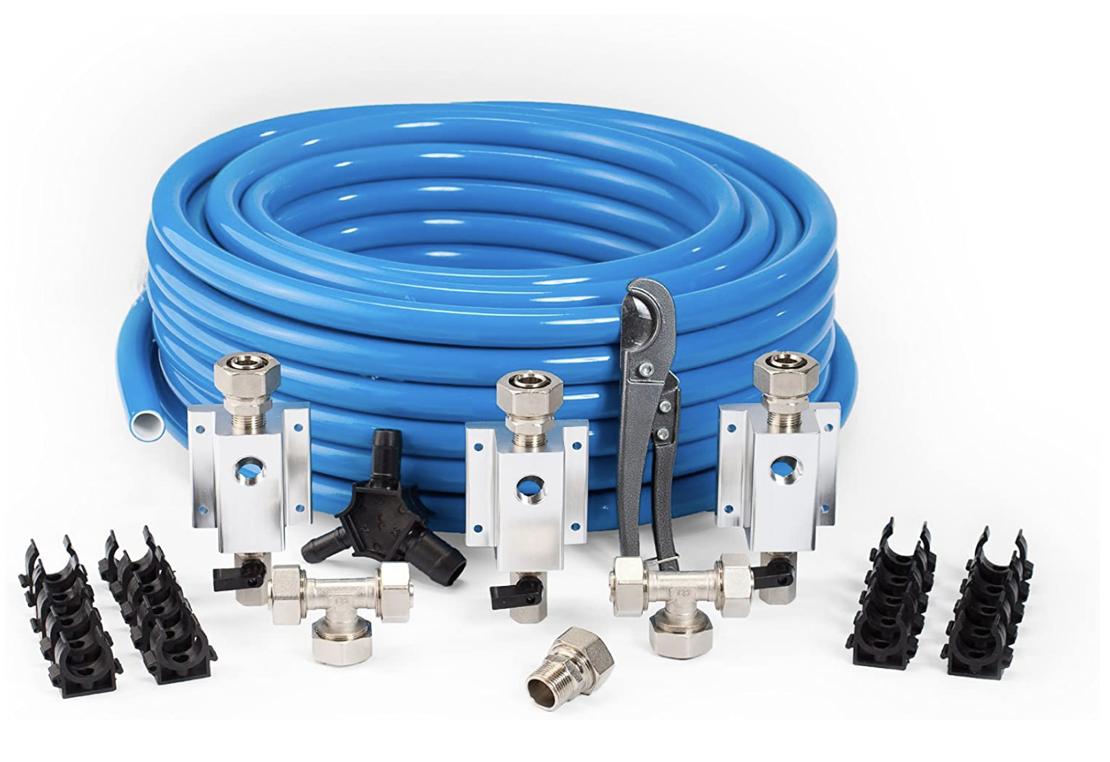
I used HDPE Aluminum Piping for my air runs. I bought two of these kits from Amazon: Maxline HDPE Aluminum Piping – I got one for the initial part of my shop, and then needed a longer run to setup the CNC machine. It was cheaper to buy a second kit than to buy the pieces individually.
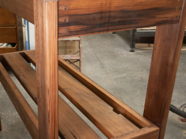
There are two important things to do when running the pipe: have it run “downhill” with a drain at the end, and have a loop up wherever you put a drop. The loop can easily be seen in this photo below going up and back down, behind the green PVC piping. This is the air drop for my CNC. The green PVC is 6″ DWV pipe for my dust collector.
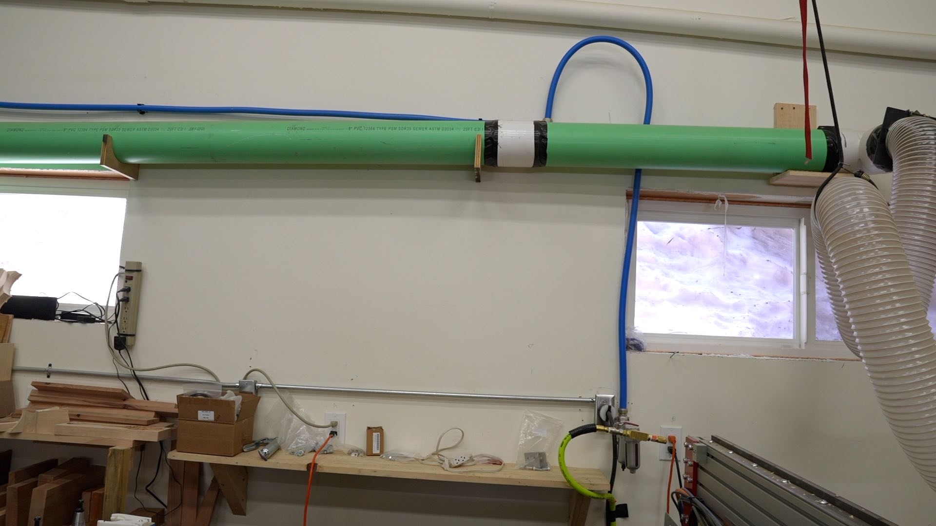
At the air drop, I have two “filters”. First a water separator, and then an air dryer. From there I have a flexible hose that goes into my Spindle Control Box.
General Parts List
These are all the parts I bought; some where included in the CNC Depot Avid Control Box, but I added a lot more myself. Most I got from Automation Direct (no affiliation or sponsorship), but stuff I couldn’t find I got from Amazon (these are affiliate links for what I actually bought)
- HDPE Aluminum Piping – I used 3/4″ tubing, but 1/2″ might work fine too.
- Water Separator (I have three in my shop):
- Air Dryer
- Flexible hose from the wall to my CNC:
- Solenoid valve – AVS-5111-24D (Comes with the CNC Depot Package)
- Solenoid valve – AVP-31C1-24D (1 or 2 needed)
- Distribution block – MRA-3CB
- Regulator 7-130psi range – AR2-323 (2x needed for HITECO, one for S30C)
- 4mm tubing (HITECO only)
- 6mm tubing (HITECO only)
- 1/4 tubing (Provided with CNC Depot package)
- 4mm by 1/8″ NPT push connects (HITECO only)
- 6mm by 1/8″ NPT push connects (HITECO only)
- 1/4″ by 1/8″ NPT push connects
- 1/4″ by 1/4″ NPT push connects
- 1/4″ NPT plugs
- 1/8″ NPT plugs (counter sunk head) – plugs the back of the solenoid
- Momentary Switch Button (S30C only, not tested!)
- Two Conductor Shielded Wire (I used a CAT5 shielded cable..which I don’t really like…super thin)
- Pneumatic Pressure Switch QPF-N1 (Adjustable)
- Additional Relay – I bought 2x for the HITECO build, 1 came with the package.
Drawbar Air Diagrams
In general reference the official Avid CNC Wiring Diagram and CNC Depot’s Directions (PDF link in the middle of the page). I based my HITECO pneumatic circuit and wiring off of the HITECO’s recommended schematic, which I’ll include below:
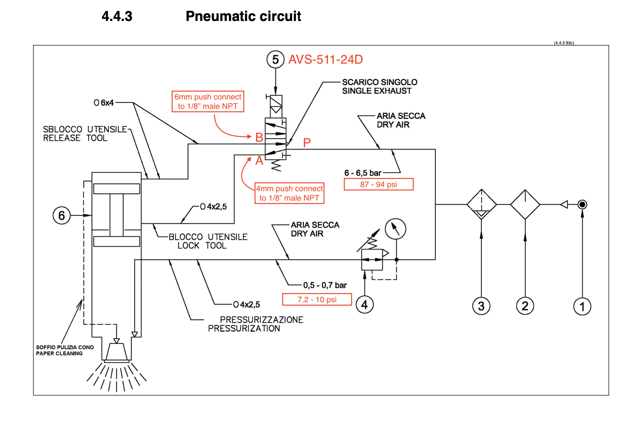
My specific setup looks like this, which also works for the S30C:
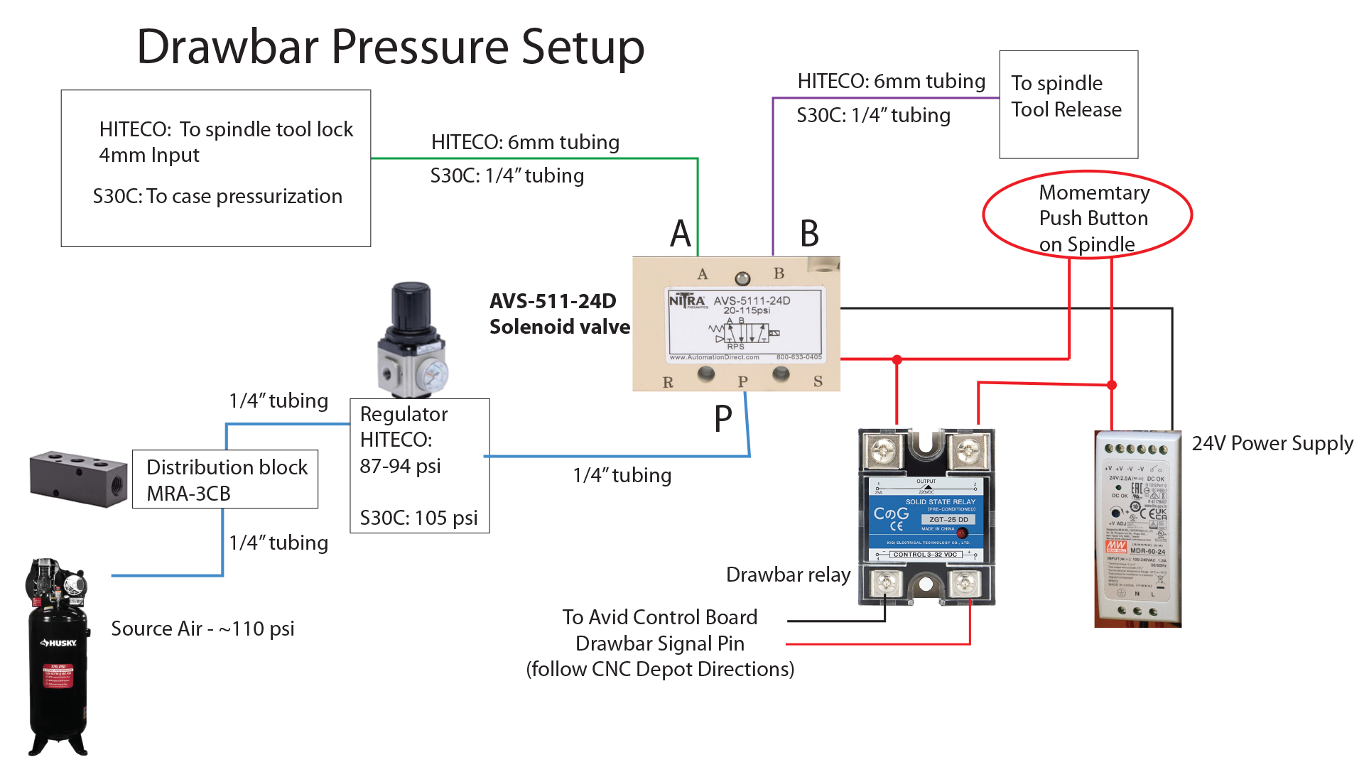
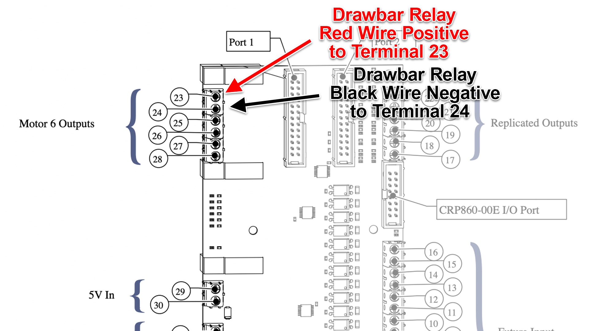
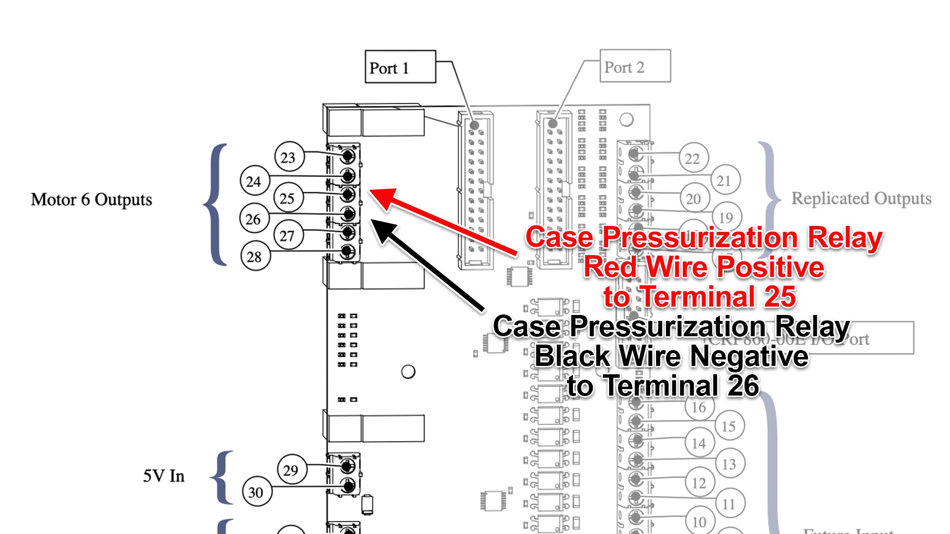
The relay wiring goes as follows to the Avid Control Box on the red breakout board.
Air Pressure Check Diagram
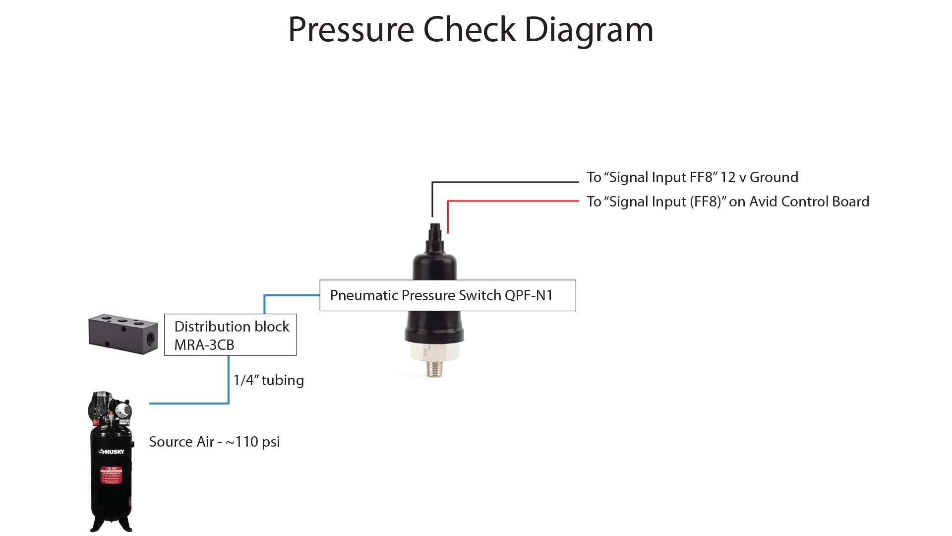
This is optional, but highly recommended. The air pressure check is a simple pneumatic switch that tells Mach 4 if the air pressure is on and high enough to do a tool change. Without this, the tool will attempt to release and might break the tool fork off as it pulls up because it didn’t actually release.
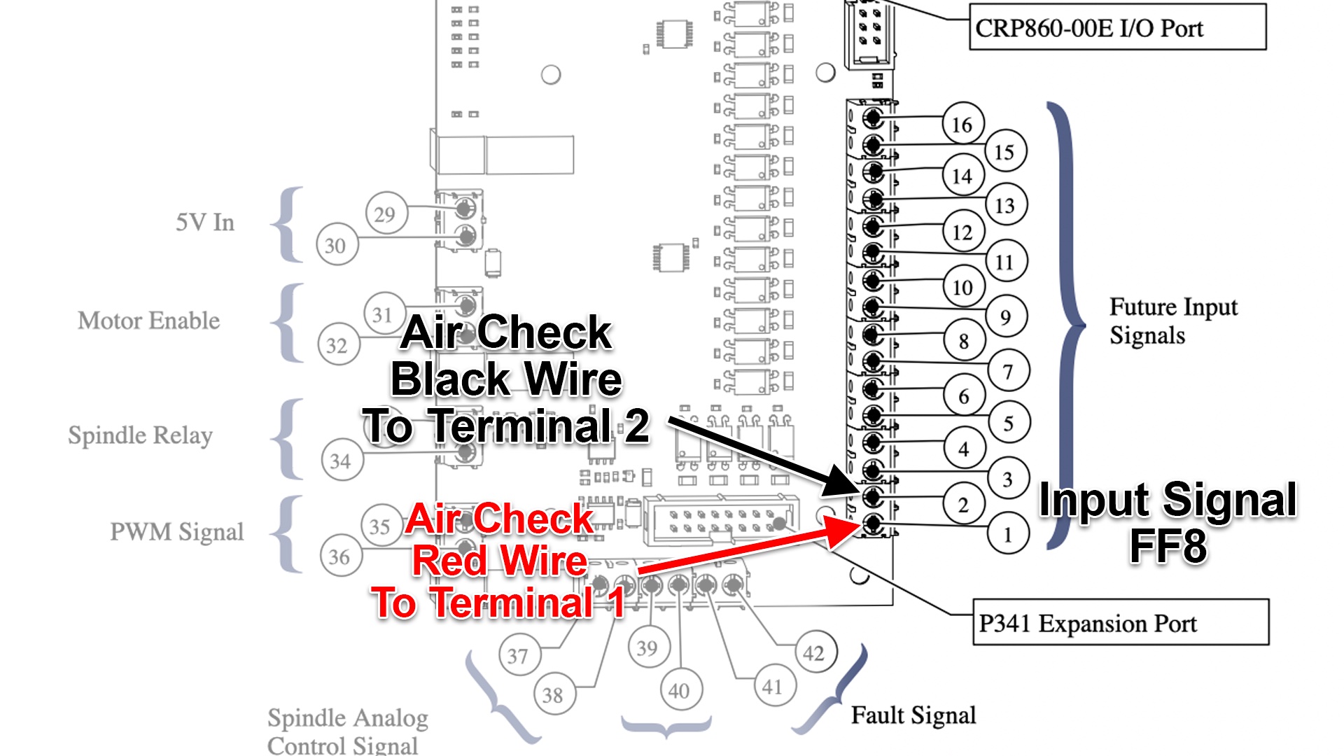
The wires go into FF8 on the signal inputs on the Avid Control Board, shown below the diagram.
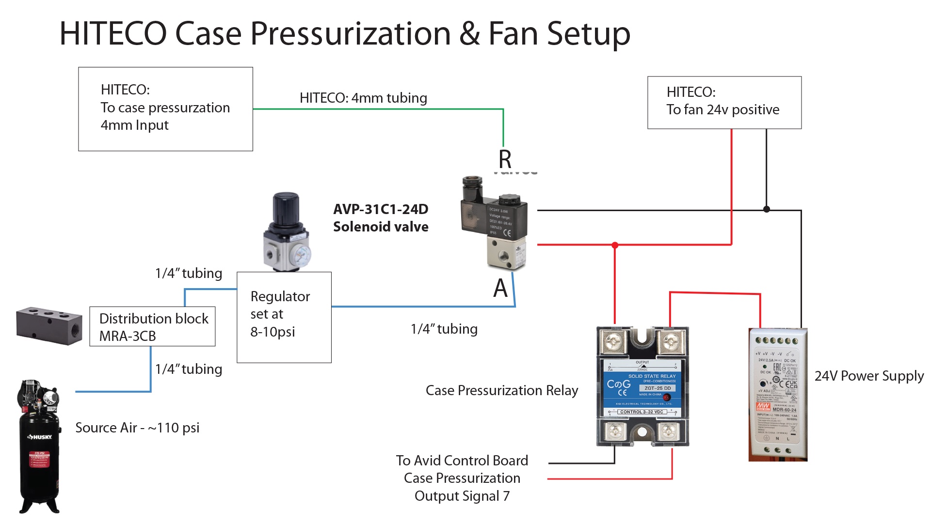
Case Pressurization and Fan Control
The HITECO has a separate case pressurization line that the S30C doesn’t really have. It does have a line, but it is already fed from the Drawbar Air Diagram. The HITECO needs a separate lower air pressure for this input. I wired it up to a relay that only turns on the case pressurization air when the spindle is actually running. It also controls the fan on the spindle.
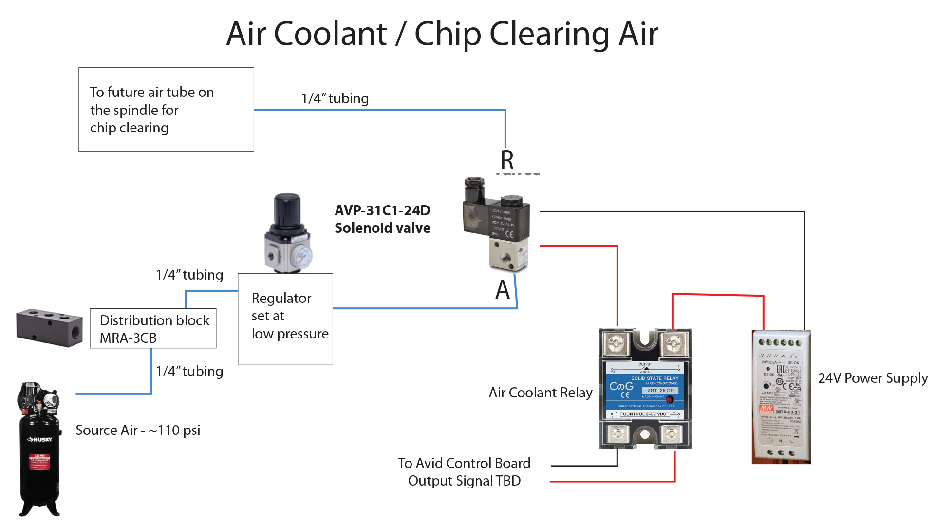
Air Coolant / Chip Clearing Air
I’m not using this yet, but I did put it in the box in case I eventually want to have some air to clear chips. It is an additional relay to control another air line.
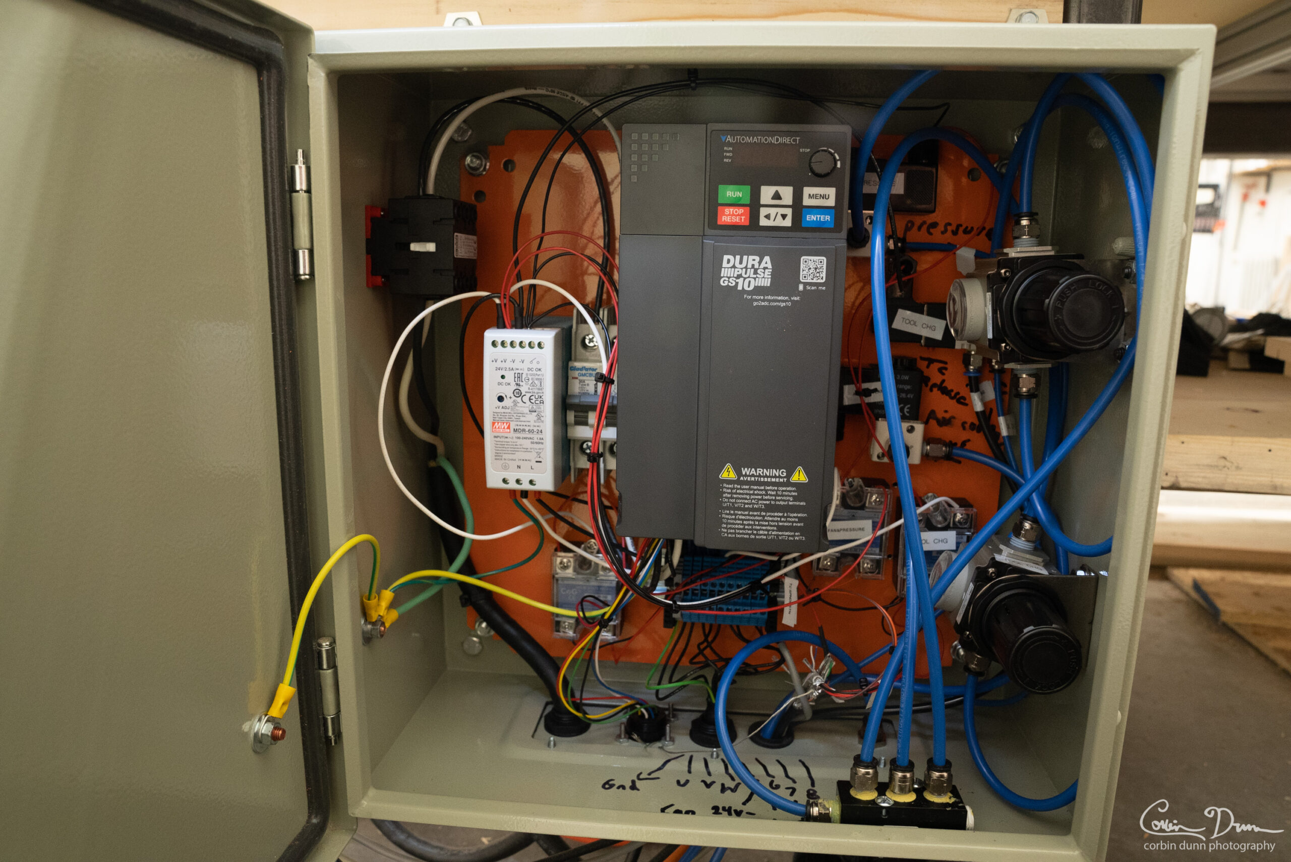
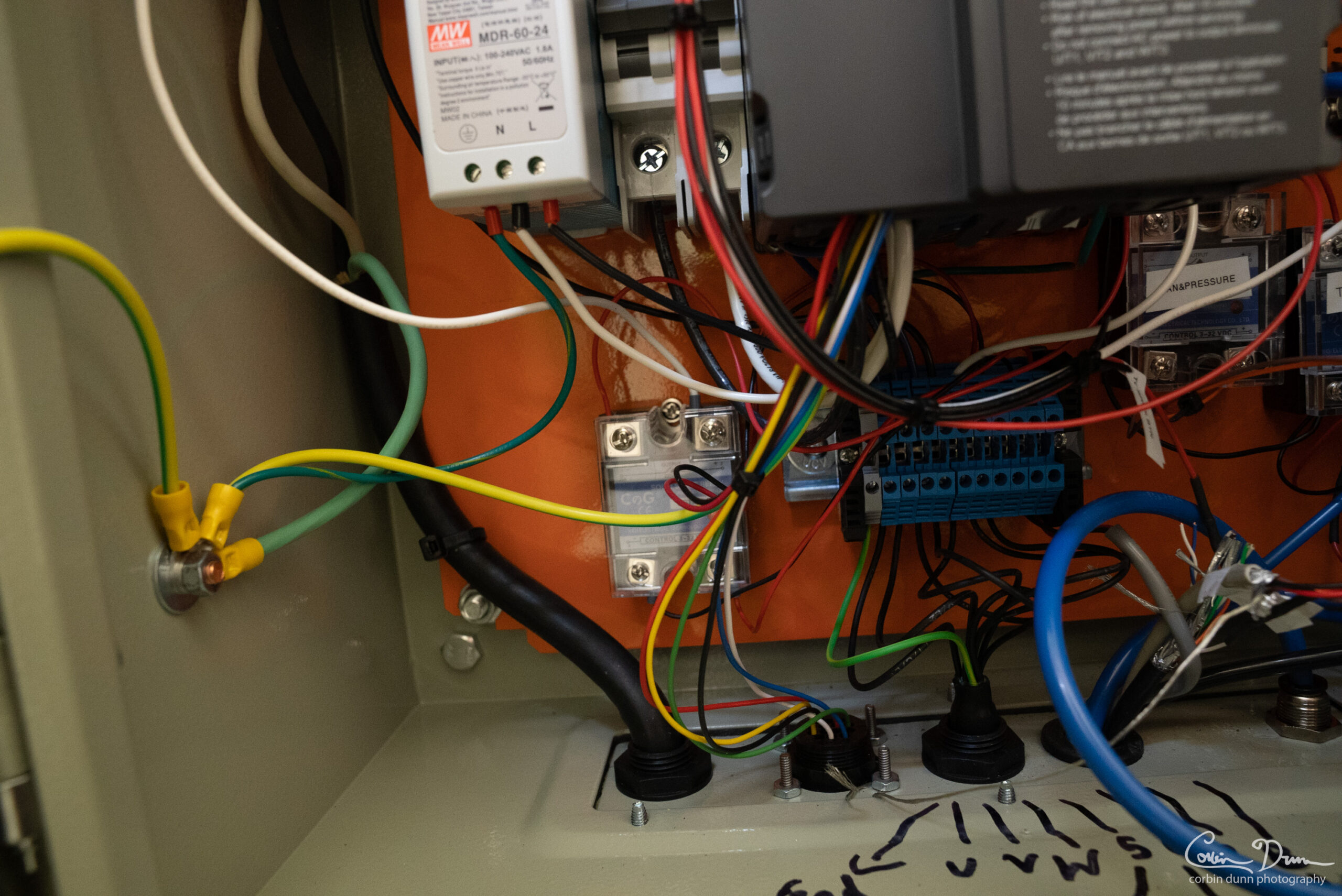
My Spindle Box
Here are photos of my spindle box. The overall layout. If I were to do it again, I would put the pressure regulators on the outside of the box; it would be a lot easier to adjust them.
Bottom left of the box; I added the relay on the bottom left for the “air coolant” which I am not using yet.
Bottom right: I have two relays, the Fan and Case Pressurization relay, the Tool Change Relay, one of the pressure regulators. In the top/middle is the “Air Coolant” solenoid (not used yet).
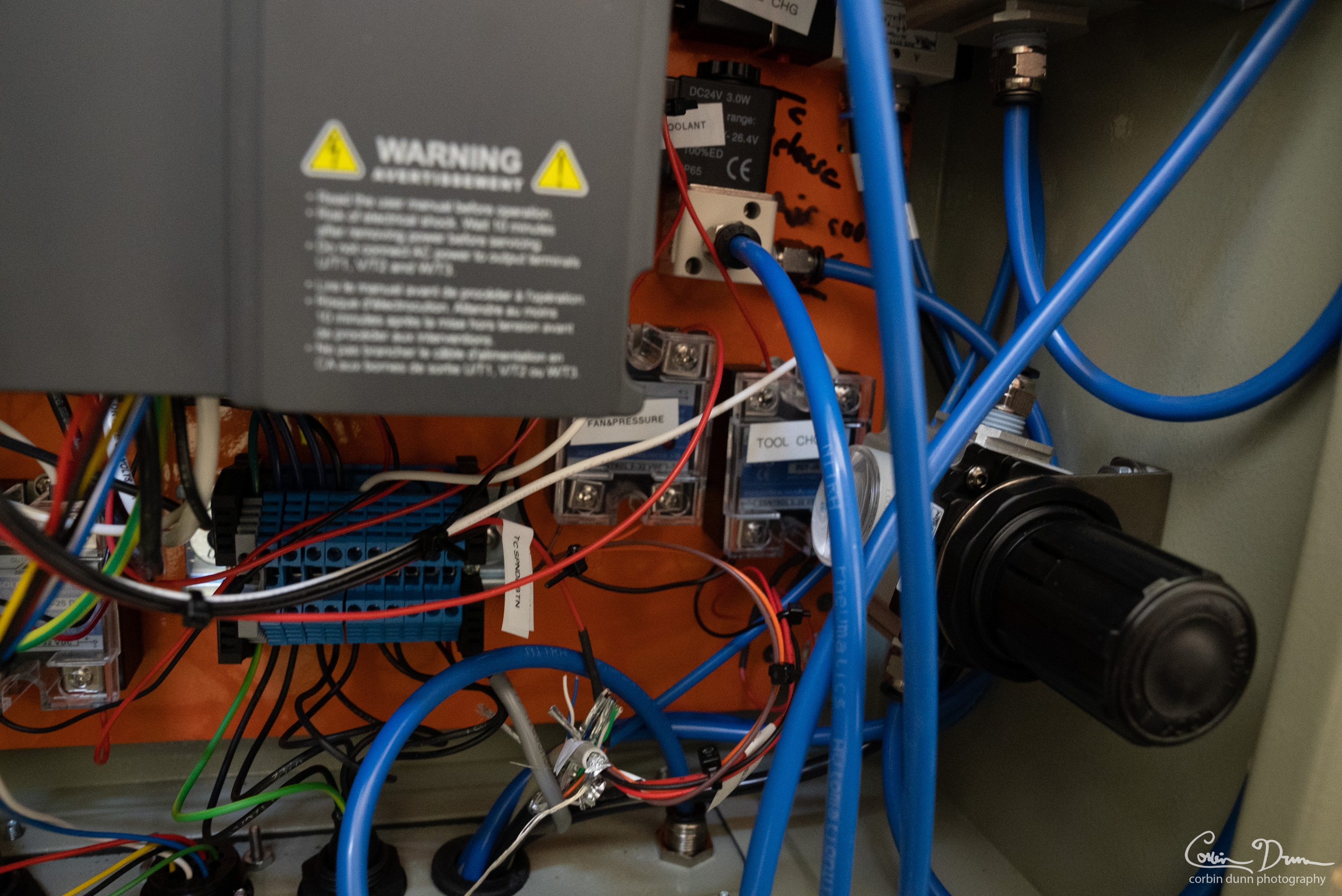
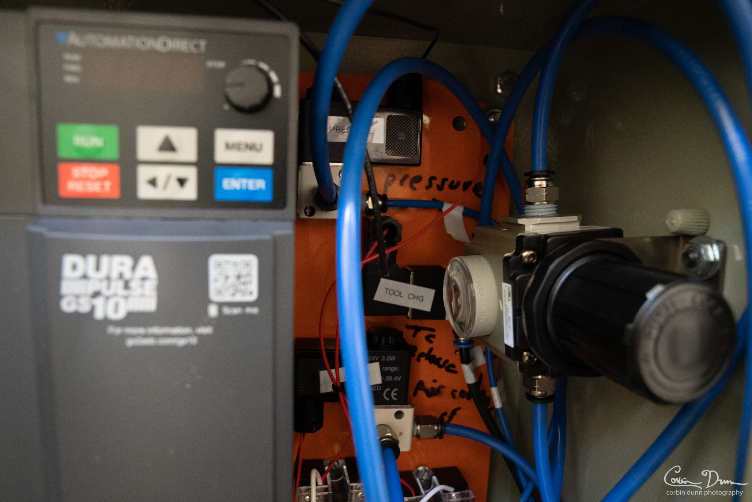
The top right: On the right is the second air pressure regulator. On the top is the “case pressurization” solenoid. In the middle is the Tool Change (TOOL CHG) solenoid.
Conclusion
Once you get all the hardware setup, visit my Mach 4 ATC Setup page to do all the software side of things (Inputs, Outputs, Relay control, etc).
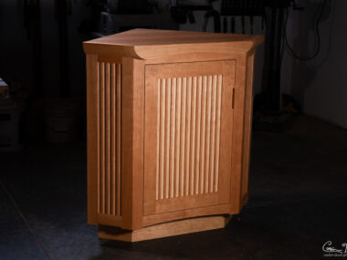
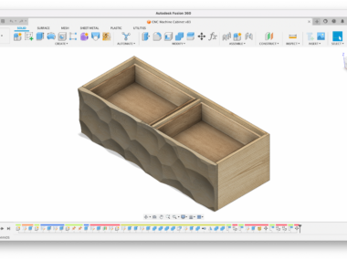
In the next article I’ll cover making my custom DIY ATC Tool Rack.


[…] one of my last posts, I discussed how I setup the hardware for my ATC on my Avid CNC. This video describes the software side of things. I’ve been working on this software for […]