Charger mounted, BMS install in progress
The charger (Manzanita Micro PFC30) is mounted on two angle iron pieces that are mounted to the car chassis in the front trunk:

Notice the clear lexan cover on top of the batteries.
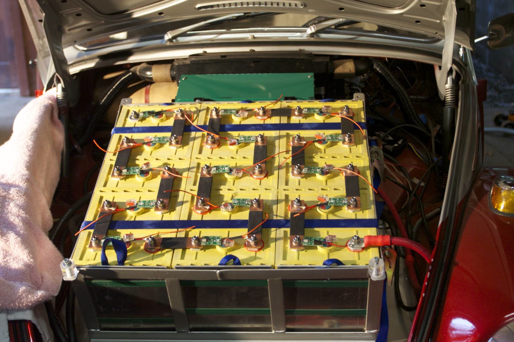
Rear pack with hold down strap. It’s breaking point would be past 7g’s (based on the weight of the batteries). Each group of cells is strapped together with the end plates:

BMS installation work in the front. I’m using solid bus bars, which might be controversial in the EV world. Ideally, bus bars that have some sort of play should be used in case the cells swell. I’m opting to not do that, as I have seen other installs that use solid aluminum bars and seem to be fine. I’m also not planning on abusing the cells, so they shouldn’t swell.
Tonight I spent about 3 hours running wires from the front to the back of the car.
I hope to get the BMS all interconnected by Friday night, and hopefully the replacement boards will arrive and I can charge it!
The lexan cover: I went with something a little too flimsy — I think it is 3/16″, but I need to double check. I wish I would have gone 1/4″, or larger, and I might replace it. Unfortunately, lexan (polycarbonate sheet) is hell of expensive. Here’s the rear sheet before I uncovered it:
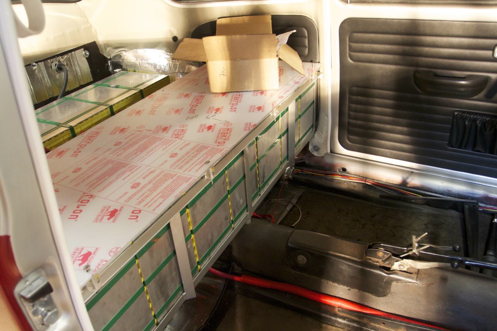
It sits on little acrylic column posts with a hole drilled in the middle. A bolt is then put in, and the top of the battery box is tapped to hold it down:
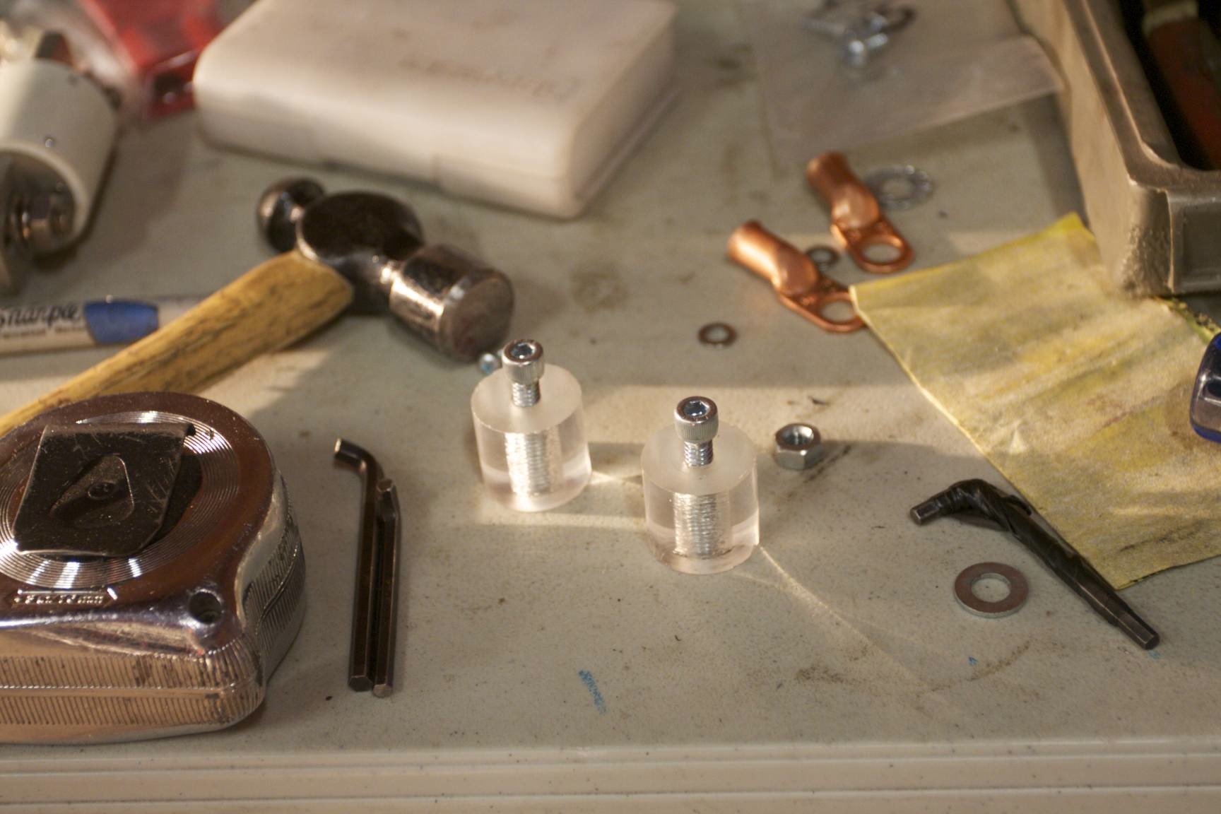
The posts were cut with the horizontal metal band saw and then drilled on the lathe. A cleanup pass on the end was done to bring them all to the equal height. I did a few, but Aaron was over last weekend and made a bunch for me (thanks man!)
Other completed things: the pack is all wired, with High Voltage wires running from the front to the rear of the car. The reside inside the car, on the passenger side. To avoid signal noise and interferance, all low voltage wires are on the driver’s side.
Despite the batteries not being charged, I couldn’t resist putting the car up on blocks and hitting the throttle a little — it came alive! I discovered I had the DC-DC converter always wired “on”, and had to get another relay so it would only be on when the key was flipped on. Some people have it always on, but I prefer turning it off to avoid it draining the high voltage pack.